Denbigh introduced UML in the previous course. This lesson will provide an overview to UML and introduce CRC (Class Responsibility Collaborator) cards. Basic guidelines to Object Oriented Analysis and Design are provided. In addition, an example design will be provided on-line with some of the resulting digrams. The in-class case study will be described and the Artisan Real-Time Studio software will be demonstrated.
Larman (Applying UML & Patterns, An Introduction To Object Oriented Analysis & Design) states "The most single important ability in object-oriented analysis and design is to skillfully assign responsibilities to software components".
The choice of responsibilities affects robustness, maintainability, and reusability, of software components.
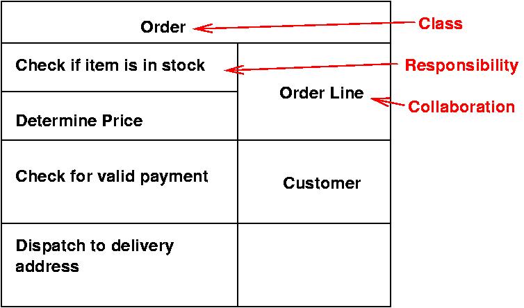
Two renowned Smalltalk programmers from Tektronix in 1980 came up with a simple method to teach key ideas in object technology. The CRC cards while not specifically a part of UML are directly usable with it.
Use CRC cards to help explore an interaction between classes, typically to show how a scenario is implemented. After it is figured out, document it with a UML interaction diagram.
There are obstacles to the OO paradigm shift.
This section uses a simple case study as an example. Briefly, this case study is a next generation Point Of Sale system (POS). A POS system is a computerized application used (in part) to record sales and handle payments; it is typically used in a retail store. It includes hardware components such as a computer and bar code scanner, and software to run the system. It interfaces to various service applications, such as third-party tax calculator and inventory control. These systems must be relatively fault-tolerant; that is, even if remote services are temporarily unavailable (such as the inventory system), they must still be capable of capturing sales and handling at least cash payments (so that the business is not crippled).
A POS system increasingly must support multiple and varied client-side terminals and interfaces. These include a thin-client Web browser terminal, a regular personal computer with something like a Java Swing graphical user interface, touch screen input, wireless PDAs, and so forth.
Furthermore, we are creating a commercial POS system that we will sell to different clients with disparate needs in terms of business rule processing. Each client will desire a unique set of logic to execute at certain predictable points in scenarios of using the system, such as when a new sale is initiated or when a new line item is added. Therefore, we will need a mechanism to provide this flexibility and customization.
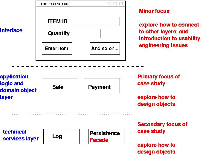
Figure showing sample layers and objects in an object-oriented system for the case study.
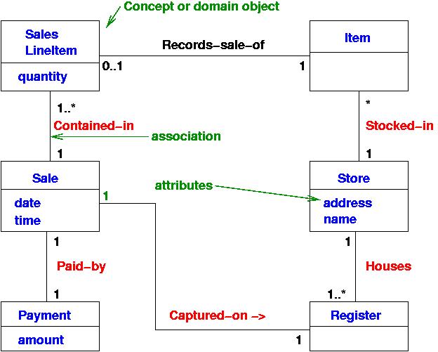
A partial Domain Model is provided for reference.
Nine fundamental responsibility assignment principles (from GRASP patterns) General Responsibility Assignment Software Patterns:
Assign a responsibility to the information expert - the class that has the information necessary to fulfill the responsibility. Given the following partial domain model for the POS case study, the question to ask is Who should be responsible for knowing the grand total of the sale?
Associations of Sale By Information Expert, we should look for that class of objects that has the information needed to determine the total. The above picture is the Domain Model. If a Design Model is not available, you would look here and attempt to use (or expand) the representations to inspire the creation of corresponding design classes.
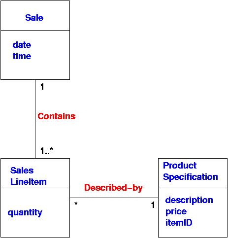
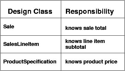
What information is needed to determine the grand total? It is necessary to know about all the SalesLineItem instances of a sale and the sum of their subtotals. A Sale instance contains these; therefore, by the guideline of Information Expert, Sale is a suitable class of object for this responsibility; it is an information expert for the work. We add a getTotal() method to the Sale class. But, we defined a subtotal and now we need to ask what information is needed to determine the line item subtotal? SalesLineItem.quantity and ProductSpecification.price are needed. The SalesLineItem knows its quantity and its associated ProductSpecification; therefore, by Expert, SalesLineItem should determine the subtotal; it is the information expert. We therefore add a new method getSubtotal() to the SalesLineItem class. The following table summarizes these responsibilities.
In object-oriented software land, all software objects are "alive" or "animate", and they can take on responsibilities and do things. Some synonyms for the Information Expert are:
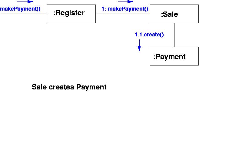
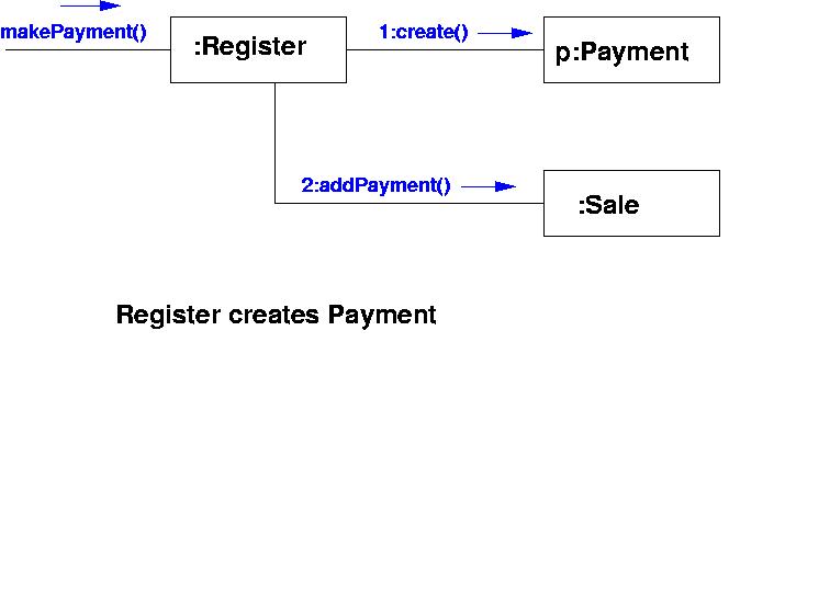
Assign class B the responsibility to create an instance of class A if one of the following is true:
Assign a responsibility so that coupling remains low. Choose low coupling as compared to high coupling. Sub-class inheritance is a form of strong (bad) coupling. But, too little coupling is also bad!
Assign a responsibility so that cohesion remains high. Same figures hold. If Sale creates payment, then the cohesion of all remains high.
Assign the responsibility for handling a system event message to a class representing one of the following choices:
When related alternatives or behaviors vary by type (class), assign responsibility for behavior -- using polymorphic operations -- to the types for which the behavior varies.
Corollary: Do not test for the type of an object and use conditional logic to perform varying alternatives based on type.
Assign the responsibility to an intermediate object to mediate between other components or services so that they are not directly coupled.
Assign a highly cohesive set of responsibilities to an artificial or convenience class that does not represent a problem domain concept -- something made up, to support high cohesion, low coupling, and reuse.
Identify points of predicted variation or instability; assign responsibilities to create a stable interface around them.
A use case is a set of scenarios tied together by a common user goal. A scenario is a squence of steps describing an interaction between a user and a system. So if we have a Web-based on-line store, we might have a Buy a Product scenario that would say this: The customer browses the catalog and adds desired items to the shopping basket. When the customer wishes to pay, the customer describes the shipping and credit card information and confirms the sale. The system checks the authorization on the credit card and confirms the sale both immediately and with a follow-up email. The scenario is one thing that can happen. However, the credit card authorization might fail. This would be a separate scenario.
A simple format for capturing a use case involves describing its
primary scenario as a sequence of numbered steps and the
alternatives as variations on that sequence. An example follows:
Buy A Product
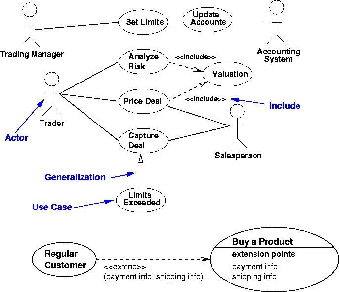
See the Figure.
UML provides and Artisan provides even more examples of Use-Case diagrams. See the on-line example or UML diagrams for examples.
Artisan is a BIG package with many many tools and options. We will use the alarm case study to introduce the main focus of the package. In addition you will want to use the help features supplied by the package. UML does not represent a process. In order to discuss a process in this course, we will use the Artisan process.
The old waterfall process model has generally been discarded in favor of some version of the spiral process model. Some of these adaptations are:
The philosophy underlying the incremental approach is embodied in the "80:20" rule: It should be possible to deliver 80% of system functionality in 20% of the overall time. (And a corollary to this rule is the last 20% of the functionality takes infinite time.) As software developers we tend to spend 80% of our time "gilding the lily" in elaborating and polishing the design to accommodate detailed changes and introducing cosmetic niceties. This is evidenced by the time honored reply of "95% done" by the developer in response to the manager's question of "How far to go?".
UML was chosen by Artisan as the basis for the notation and semantics in Real-time Perspective because:
UML is not a sufficient basis for describing Real-time object oriented models because it has weak or lacks capability in the following areas:
Hardware is constructed in distinct layers. The lowest layer consists mostly of integrated circuits. The next layers are the printed circuit boards and so on. The purpose of object technology is to build software in analogous fashion to hardware by assembling objects at different abstraction layers. This provides the following benefits:
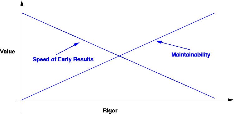
All software processes can be considered to be somewhere on a spectrum of rigor with no method hacking at one extreme and processes based on the use of formal mathematical specification at the other end as illustrated in the following diagram.
We introduced the concept of an object in the previous course. But here is a brief overview related to Artisan.
Booch (1996) identifies four major elements of Object Orientation
An object is something which you can do things to and which can do things for you! It is a package of data and functionality, that bind together to fulfill a coherent set of responsibilities. Each object has a unique identity.
An event is an asynchronous occurrence in the real world, which is or relevance to the system being built. An input event is one which the system accepts from the real world and responds to; and output event is one which the system generates in order to effect the real world. Input events are of three types:
As systems become larger and in cases where the system is being assembled from a number of smaller systems (sometimes called components), it is useful to view the system as a set of services and clients in a service-based architecture. Typical service categroies are:
Traditionally, objects have been seen as homogeneous, i.e. an object is an object and may have any types of responsibility. Current thinking has suggested that actually there are three primary stereotypes of object. Originally, this classification came from the Model/View/Controller paradigms in Smalltalk, but more recently Jacobson (Jacobson, 1992) has suggested the stereotypes entity, interface and control, and these seem to have been readily adopted.
More on this will be given on day 4 and 5, but in overview the Real-time perspective bridges the concepts of: