|
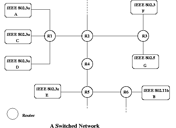
In a large network, efficiency is obtained by using complex connections that provide more multiple paths for a packet. For example, if you send a packet from A to B in the network, the packet has to go from your station to a router, where it is directed toward the correct destination. Router R1 has to recognize that the path to B lies through router R2; R2 has to route the message to R4, not to R3 and so on. As it progresses, it may pass over many different physical layer connections and through many different routers. At each of those, a decision has to be made as to where the packet should be sent. If a packet is directed to the wrong place, it may not be deliverable, or it may have to be returned and re-sent in a different direction.
While they are often spoken of in the same breath, switches and routers have different objectives, and those two objectives, switching and routing are key to the behavior of a network. Switching is the process of moving a packet of information through the network according to a uniform set of rules. Routing is the collection and application of information that allows the switched packet to follow the correct and hopefully, fastest path to the destination. In general, switches do only switching, while routers do both, although there are devices that cross the barrier and do combinations of the two. Switching is the activity that takes place when a device in the network directs an incoming packet to an outgoing port.
Practically speaking, this means that a switch or router takes a packet that arrives on one port and directs it to be output on another port. There are three types of switching:
If a subnet uses circuit switching, the transfer of information begins with a connection that establishes a route through the network and any information that is sent follows exactly that path. As each piece of data moves through the network, each router knows exactly what to do with it at each step. This would be like sending a series of trains across the country with all of the switches set before you start. At each switch, the decision is already made about what to do. At the physical layer, DS carriers like T1 use circuit switching; a telephone call gets assigned to a particular channel in the T1 frame and each voice sample uses exactly that channel. It is decided in advance and does not change.
If a subnet uses packet switching, there would be no connection, and each unit of information would switched independently from any other packet in the stream. This is like sending the series of trains, but at each switch a decision is made as to the best path to take based on current information. There are obvious advantages to circuit-switching; once the connection is set up, it is fast since all of the switching decision have been made and all of the necessary resources, like memory, can be assigned in advance. On the other hand packet switching can adapt to changing conditions in the network and if a switch or router fails, the connections through it aren't broken. Also, if you have very little information to send, packet switching doesn't require the overhead of setting up a connection.
Virtual circuit switching will be discussed later, but it is a way of making a packet-switched network appear to be circuit-switched. A given network of routers and switches is either circuit-switched or packet-switched, as there are difficulties in having them work together. However, it is not uncommon for different types networks to be linked together through gateways.
For example, Router R2 might have a routing table that looks like this:
A R1 B R4 C R1 D R1 E R4 F R3 G R3
Of course, this only works if the other routers have tables that route from their own viewpoint. If R2 sends packets destined for B to R4, then R4 needs to forward it to R5 and R5 needs to forward it to R6 and then R6 can deliver the packet to the required local area network.
This scheme poses several questions:
A virtual circuit is a path through a packet switched network that requires every packet to follow the same path. The VC is established by an initial connection where all the routing decisions are made and all the resources are allocated. For example, suppose in the previous example that host 10 on network A opens a virtual circuit to a host 20 on network B. An application on host 10 on A initiates the connection with a connection request to the network layers that effectively says "please open a virtual circuit to host 20 on network B." The network layer creates the virtual circuit and provides the application with an identifier that is like a socket or file descriptor. Any message sent to that virtual circuit is routed to the destination by the rules established at connection setup.
In this example, suppose that the application with process id 1234 makes the connection request. The network layer at host 10 finds that the destination is not in A, so it sends the request to router R1 and makes an entry in its virtual circuit table. This might look like this:
To VC id 1234 0 R1 5
There appears to be no good reason for the choice of virtual circuit identifiers, and there need not be. All that matters is that there can't be an ambiguity as to where a packet should go.
Next, R1 sees that the destination can be reached by sending the request to R2 and forwards it, making an entry for it in its local virtual circuit table.
To VC id Host 10 5 R2 3
Then R2 decides that the request must be forwarded to R4, so it forwards it and makes an entry in its table:
To VC id R1 3 R4 2
R4 decides that the request must be forwarded to R5:
To VC id R3 2 R5 9
R5 decides that the request must be forwarded to R6:
To VC id R4 9 R6 1
R6 finally finds host 20 on network B and forwards it and makes an entry in its virtual circuit table:
To VC id R6 1 Host 20 5
Finally, host 20 finds the right application to send the request to:
To VC id Host 20 5 Process 5467 6
Assuming that the process receiving the request accepts the connection, the acknowledgement of the connection follows backwards through the path and each router formalizes the route. If the process refuses, the refusal backtracks through the network and each router removes the entry from its tables.
This is similar to a TCP connect/accept process. When the acceptance finally makes it back to host 10 on network A, the virtual circuit is established. Now track a message from the application on host 10 to the application on host 20. At each step, the sender along with the virtual circuit in the packet tells the router where to send it and what virtual circuit number to put in the packet. So the virtual circuit number doesn't stay constant as the packet moves through the network.