Introduction
To objective of data communication is to transfer information from one point in the network to another with a specified level of reliability. Reliability is a measure of the accuracy of the received data, and reflects the operational characteristics of the data communication nodes and the links in the system. This is not the same as the system reliability which depends on the data communications reliability and the communication software.
There are two basic topologies that are used in data communication systems: point-to-point or direct links connect only a single transmitter and a single receiver. Multi-access or multi-point links connect multiple nodes together so that any can transmit to any of the others, although in most cases, only one can transmit at any given time.
The basics of data communication start with a signal which can be transmitted over a media. Media can be either guided which have a physical path that the signal follows, or unguided, where the signal propagates in all directions. Examples of guided media are wires and fiber optic cable; examples of unguided signaling are sound propagating in water, or radio stations broadcasting through the air.
While you can use a variety of different sources for signals (sound, touch, smoke), we will focus on geomagnetic signals and include light in that category. An geomagnetic signal is a generated voltage that can move through the desired media. For example, you could have a simple signal like this, which is simply a constant voltage of 5 volts.
 |
The problem with this signal is that is can't deliver much information. If you were at the receiving end, you could tell that the signal was there or not; one bit of information. Clearly the signal has to change in some way to actual transmit data. Also of importance is the concept of time; the signals we are interested in change over time.
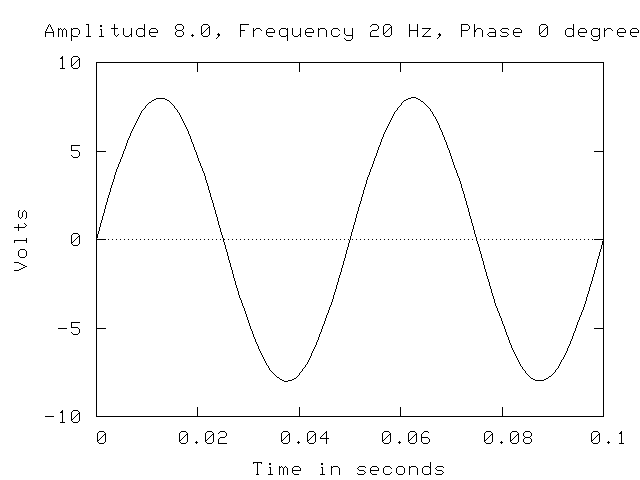
A sinusoid like this can be represented mathematically as a function of time like this:
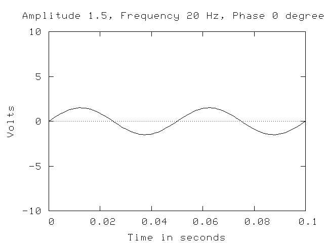
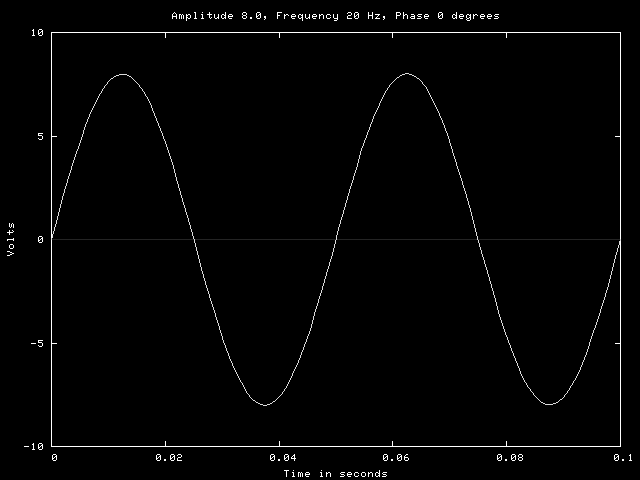
A is the amplitude of the sinusoid, f is the frequency and phi is the phase angle. The amplitude is the height of the wave, or in the practical sense, the maximum voltage of a signal. For example, the following two sinusoids are identical except for the amplitude:
The frequency defines the rate of change of the signal and is typically given in Hertz (Hz) which is cycles per second, but could also be given as the inverse frequency or period. For example, a frequency of 100 Hz is a period of 0.01 seconds. The following two sinusoids are identical except for the frequency:

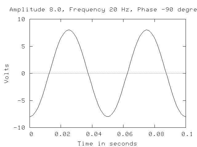
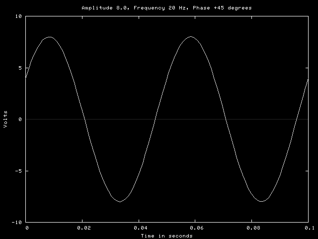
The phase angle is the amount that the sinusoid is shifted from the zero point. Two examples are shown below. The graph on the left is a sine wave that has been shifted -90 degrees, or one-fourth of a cycle to the right. The graph on the left is a sine wave shifted +45 degrees, or one-eight cycle to the left.
Each of these parameters can be modified to produce different sinusoids. Either a sine or cosine wave can be generated, but a sine wave is simply a cosine wave shifted -90 degrees so it makes no difference except in the orientation of the signal at a given point. Signals that are composed of sinusoids are called analog or continuous signals.
Since we are interested in sending signals that contain information and that information is represented by the changes in the signal, there are three choices; the frequency, the amplitude or the phase angle can be changed. For example, if the amplitude of a signal can be either 5 volts or 10 volts, these could represent zero and one. Many of the signaling systems in use today use sinusoids to transfer information. A transmitter produces a sinusoid and varies one or more parameters to represent a data stream. The receiver can convert the signal into the original data if it knows the encoding scheme used by the transmitter.
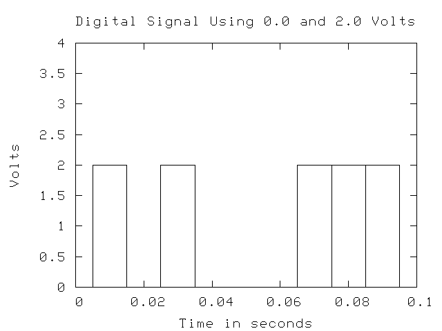
Another possibility is to use a square wave to represent the data. For example, the following signal uses two voltage levels to represent data where a voltage of 2 volts represents 1 and a voltage of 0 represents zero.
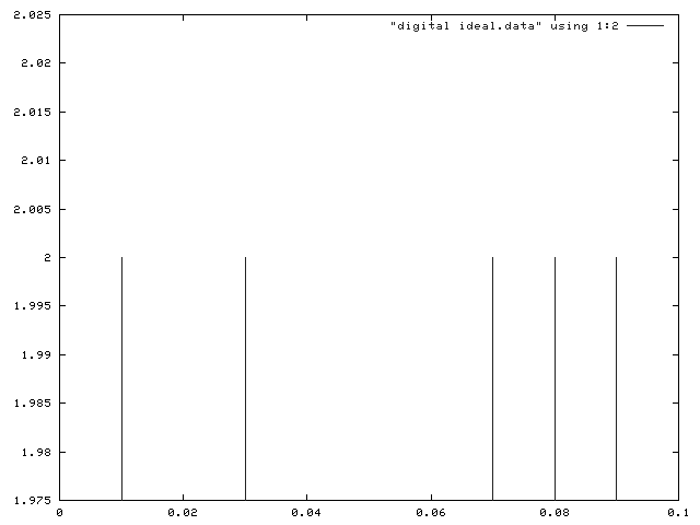
In order to get the maximum speed, you would want the square wave signal to be a narrow as possible, but you can't change voltage levels instantaneously. The ideal digital signal would be something like this:
But a typical digital signal looks more like this:
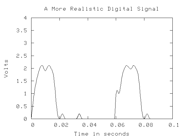
As you can see, a digital signal is not really a set of discrete values, and the value of the signal is changing more or less continuously as in an analog signal. However, digital signaling systems attempt to get as close to the ideal as possible and the methods used to encode data will nearly always use only two values for zero and one, hence the use of the term digital.
Analog Signaling
So how do you actually encode data into an analog signal? By modifying the amplitude, frequency and/or phase angle in some predictable manner. There are three basic types of analog signaling methods which depend on varying the amplitude, frequency and phase angle:
Encoding Type Variable Parameter Amplitude Shift Keying Amplitude Frequency Shift Keying Frequency Phase Shift Keying Phase Angle
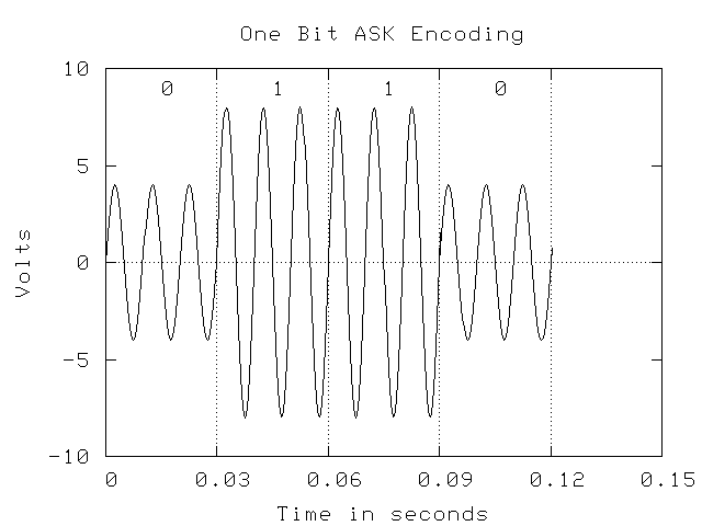
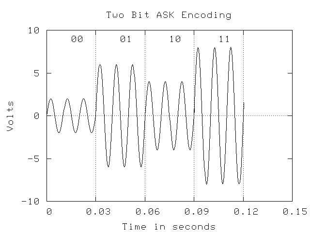
There are also more complex methods that use combinations of the three. Amplitude Shift Keying (ASK) or informally Amplitude Modulation (AM) has been used for many years in AM radio. For data transmission, a signaling system would select an encoding system for data and then assign various amplitudes to the codes. A simple example would be to assign the voltage levels 3 volts and 5 volts to the values zero and one to transmit binary data. However, you might also encode your data two bits at a time, and use 1 volt for 00, 2 volts for 01, 3 volts for 10 and 4 volts for 11.
You might think that this can go on indefinitely with higher and higher amplitudes and with smaller differences between amplitudes, but as we will see later, there are practical limitations to the resolution of different amplitudes at the receiver.
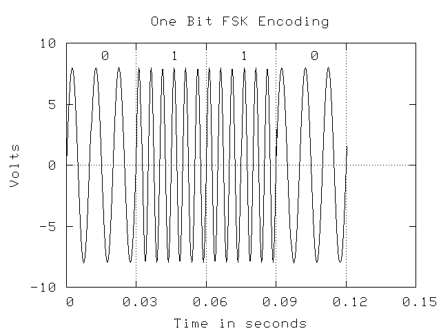
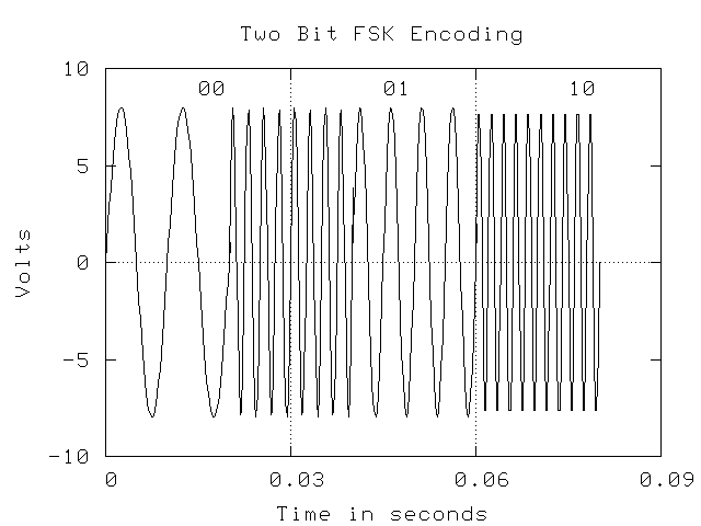
Frequency Shift Keying (FSK) or Frequency Modulation (FM) modifies the frequency of the signal to represent different encodings of data. As with AM, a practical application of this method is with FM radio. The examples below show examples of using two frequencies to represent zero and 0 and four frequencies to represent the four two-bit values. As with ASK, you can't simply add more and more frequencies; there is a theoretical and practical limit. In the examples, two full cycles of a frequency are used to represent a bit pattern.
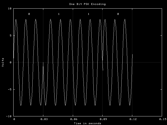
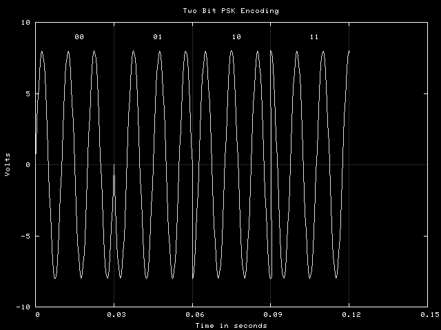
Phase Shift Keying (PSK) modifies the phase shift of a signal to represent data encodings. The examples below show the same examples as those shown above. In the first case, the phase angle are 0 and 90 degrees representing zero and one. In the second, the phase angles are 0, 45, 90 and 135, and two full cycles are again used to represent a bit pattern.
The receiver of data encoded with any of these methods has to sense that the variable parameter has changed, and then determine its new value. This is usually done by sampling the incoming signal at some rate (for example,10,000 times per second) and comparing the values. For a sinusoid with a known amplitude, frequency and phase angle, it should be possible to compare the sampled value with the expected value to see if they match. If not, compare to one of the other possible encoding sinusoids until the correct one is found. This determines the bit pattern being sent.
Obviously, there has to be sufficient signal length to collect the necessary samples and the signal cannot vary from the prescribed values unless there is a mechanism in place to pick the closest matching encoding sinusoid.
Digital Signaling
In digital signaling, it might be possible to do things with phase changes or even the frequency of changes, but usually only the amplitude of the signal is changed and typically, there are only two levels. With only two levels, only a binary information system is possible. The basic idea in digital signaling is to keep the signal encoding system very simple, but make the rate at which data is sent very fast. We will discuss this in some detail later.
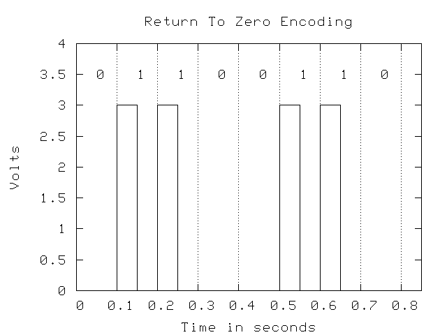
However, the way in which the bits are represented is important. For example, one possible encoding method is called Return-to-Zero (RZ), which requires that after each bit is sent, the signal returns to zero. Non-Return-to-Zero (NRZ) does not require this. Examples of each are shown below:
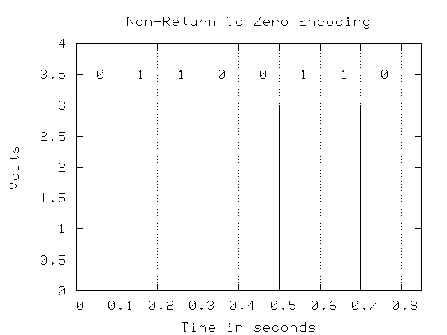
The problem with NRZ is when you get a long string of zeros or ones. The receiver has to sample the signal to see if it is high or low, and this requires a clock that indicates when a sample is due. The sender uses a similar clock to measure the length of the bits that are sent. However, it is likely that the send and receiver clocks are off slightly so that over time, the two become unsynchronized and data could be lost or misinterpreted. To overcome this problem, the receiver watches for changes in the signal from the receiver and resets its clock so that if they become unsynchronized, it is a very small amount that won't cause any errors. If there are sufficient changes there is not problem, but long periods without a change in the signal level can result in loss of synchronization. NRZ can have this problem, while RZ will not if there are sufficient ones in the data.
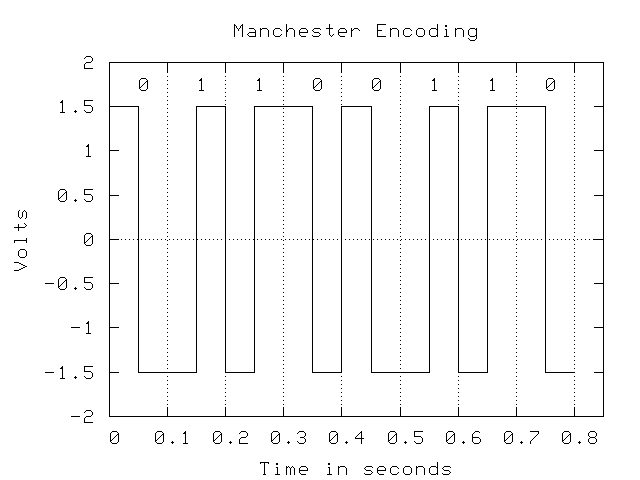
Another type of encoding that attempts to solve this problem entirely and is widely used is Manchester Encoding, which uses the direction of transition in the signal to determine the bit value: low-to-high in the middle of the bit is a one, and high-to-low is a zero. Also, Manchester encoding uses a negative and a positive voltage rather than zero. To a receiver, zero voltage can mean that the other end is disconnected, and the difference in polarity makes it easier for the receiver to recognize the signal. For example, to differentiate +3 and +5 volts the receiver has to be able to discern the amplitude accurately, while -3 and +3 volts allow a recognition of positive or negative to determine the transmitters intentions.
Bandwidth and Broadband
When we talk about a signal, it has some specific frequencies in it. For example, we could have an FSK encoding that uses 1000 HZ for 0 and 2000 Hz for 1. This signal has a bandwidth of 2000 Hz. The bandwidth is a term that is used to describe frequency range that is required to accurately represent the signal. In some cases it is the maximum frequency of the signal, but it can have another meaning as well. It is possible to take several signals and add them together to get a composite signal and still maintain their separate nature. As an example, suppose you have three different FSK signals:
900 Hz 1100 Hz 1900 Hz 2100 Hz 2900 Hz 3100 Hz
If each of these transmitted a sequence of 0,1,1,0, with an amplitude of 3 volts, you would see the expected sequence of frequencies for each. If all three were transmitted on the same medium, they would create a combined signal that looks like this:
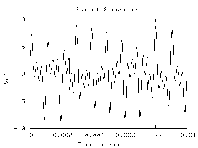
While this looks like electronic mumbo-jumbo, the receiver can reverse the process and separate the mixed signal back into its components. In this way, it is possible to send more than one signal simultaneously over a medium, as long as they don't interfere with each other by using the same frequencies. Obviously, if two of the signals used the same frequency, it would be impossible to separate the sum back into its constituent parts. This is broadband signaling, where a single medium has multiple streams of data. An example of a common use of broadband signaling is cable television, where each channel is transmitted using a different frequency band and the combined signal is carried by the coaxial cable. At he receiver, the tuned channel on receiver (TV or VCR) is filtered from the combined signal and used to drive the display mechanism. In the future, the term carrier will be used to describe a signal that might carry more than one signal, which will be called a channel. Each channel has a bandwidth which is the frequency range it needs. In the example above, each channel needs 200 Hz, plus the guard band between the channels, which is 800 Hz, so each channel has a bandwidth of 1000 Hz. In cable television, each channel has a bandwidth of approximately 6 MHz (megahertz). Note that even though the third signal uses 2900 Hz and 3100 Hz, it has the same bandwidth as the channel at 900 and 1100 Hz. So the carrier has a bandwidth of 4000 Hz (You need a guard band above the highest frequency signal) and each channel has a bandwidth of 200 Hz.
So why would you use broadband for data transmission? Suppose we have a signaling system (transmitter, receiver and medium) that has a bandwidth of 16,000 Hz. That is, it can accurately transmit signals with frequencies of 16,000 Hz, but no higher. If you felt that you could accurately detect frequency changes of 1000 Hz, you could have 16 different FSK levels (0000 through 1111). However, you could take a different approach and divide the bandwidth of the signal into 8 different groups (0-1999, 2000-3999, 4000-5999, ...). Then you could have eight different groups, each transmitting a single bit (zero or one). Why would you do that you ask? Consider this: you have 8 users, and you can either have them take turns and when they get a turn, they get to transmit using the entire 16,000 Hz, or you can let them all transmit simultaneously but only using 2000 Hz. The best choice depends on the specific situation, but if you have users that need near continuous use but at lower data rates, the broadband situation may be better. If the users don't need instantaneous response, but they want the data rate to be as high as possible, it is probably better to use all of the bandwidth for a single channel and find some other way to multiplex their use of the carrier.
To add to your repetoire of terms, when a single device handles multiple channels, it is called multiplexing. For example, we have a 16,000 Hz system multiplexing 8 channels at 2000 Hz each. As you will see, this term is widely used for a variety of things in data communications and computer networking.
Digital Signal Bandwidth
The bandwidth of an analog signal is related to the frequencies that comprise that signal, but digital signals aren't composed of sinusoidal components. However, you can readily understand the issue by considering the frequency content of a signal. Looking at the examples above, you can see that as the frequency increases, the rate of change of the signal over time increases; the corners are sharper and the lines are steeper. So a digital signal, where you attempt to change as rapidly as possible from one voltage to another represent very high frequencies. In fact, a square corner, if it was possible, would represent an infinite frequency; the rate of change of voltage with respect to time is infinite. So digital signals have very high frequency components, and hence very high bandwidths. If you attempt to transmit a digital signal through a channel which has a very low bandwidth, the high frequency components simply disappear and the signal is corrupted as shown above in the "realistic" digital signal diagram. One of the reasons that digital signals are seldom multiplexed is that each signal requires a very high bandwidth, making it difficult to multiplex them without seriously degrading the signal quality. Instead, every effort is oriented towards making the bits as narrow as possible so that the bit rate can be increased.
Transmission Degradation
The key to all this is the ability of the receiver to properly interpret the signal, which means that it must detect the amplitude, frequency and phase changes. The difficulty lies in the transmission of the data which introduces a number of factors that degrade the signal and may make it unreliable at the receiving end. The amount of degradation is a function of the type of medium used and the type of signal. These factors are:
- Attenutation
- Noise
- Delay Distortion
Impairments in a signal are often measured as a ratio of the strength of the noise in comparison to the signal. For example, the noise power might be 1% of the signal power, or the signal-to-noise ratio is s/n = 100. Typically, this ratio is expressed in decibels, where a decibel is 10 times the base 10 log of the ratio. If the signal power is 10 watts and the noise power is 0.1 watts, you have a signal-to-noise ratio of:
Attenuation
This is the gradual reduction in the amplitude of the signal due to resistance losses in the medium that carries the signal. This becomes a problem when the signal becomes so weak that the receiver can no longer reliably determine the information content. Attentuation is worse in media that has a higher resistance, worsens over distance and is more pronounced for higher frequency signals. Network designers would of course like to use the highest possible frequencies, the lowest cost media and the longest possible media links, but these are competing goals. Typically they have to settle for some compromise solution.
One solution to the attenuation problem is to amplify the signal regularly during transmissions. An amplifier receives the incoming signal and boosts the energy. For example, if a signal is supposed to be 0 to 5 volts but has attenuated to zero to 2 volts, it can be amplified. The problem is that if there is any noise in the signal, it also gets amplified, which can result in a signal which has sufficient power, but the information content has been destroyed. Since the amount of noise in a signal is also likely to increase as distance increases, this makes amplification a solution with some limitations.
Digital signals have an advantage here. Since there are only two possible values - on/off or high/low, the amplifier simply has to detect if the signal is high or low and then generate a corresponding signal. If the incoming signal is readable, it can be regenerated exactly as sent, with no noise. This process is called repeating rather than amplification is distinguish the two.
Noise
Noise is a condition where the voltage in the signal is modified enroute. The signal should be a smooth change from low to high and back again but noise changes this by changing the voltage in unpredictable ways. For example, a negatively charged burst of energy could penetrate the media and when added to the signal, reduce its amplitude.
There are a number of types of noise; thermal noise is caused by thermal motion of electrons in the media itself. Thermal noise is impossible to remove except at absolute zero. Impulse noise is the result of electromagnetic fields generated by light fixtures, motors and other electrical devices. A typical impulse signal has a particular energy level, length of time and frequency band and its impact on the signal depends on all of these. If the frequency range does not overlap with the signal, it has minimal impact. Impulse noise of often not a significant problem for analog data, as the signal contains enough information to be recovered, but for digital data, it might completely destroy one or more bits. Inter modulation noise is the result of non-linear effects caused by poorly designed equipment and is relatively rare. Crosstalk is familiar to people who have used a telephone and heard a third party conversation. It is the result if coupling between different circuits and is a minor problem in modern systems.
Noise occurs as bursts of energy, not as a continuous source. These bursts might be very short, on the order of nanoseconds, or they could be long, on the order of seconds. If a burst of noise impacts a signal, it will disrupt the signal for some period of time that is related to the length of the burst. If the encoded bits in your signal (digital or analog) are 100 ns long, a burst of 1 ns is not likely to damage the bit beyond recognition, but a noise burst of 100 ns is more likely to do serious damage.
Delay Distortion
Delay distortion is problem of guided media (wired, optical cable) and describes a problem where the velocity of propagation of a signal varies with the frequency. Specifically, the mid-range frequencies in a signal travel faster than either the high or the low frequencies. The effect is that over a given distance, there is a distortion of the signal as the various frequencies get out of synchronization. Practically, this means that the information content has to be long enough (in time) to insure that the structure can be discerned even though the signal may be distorted, and distances will be limited.
So there are a number of possible degradations that might degrade a signal. The upshot of this is that there are some significant limitations on how much data can be transmitted over a communications channel. Attempting to go to far or too fast will eventually be limited by these problems, although reducing them is a major focus of research in the data communications industry. In the previous section the example was a signaling system with a bandwidth of 10,000 Hz. This represents a particular hardware configuration over a particular distance and with certain noise conditions.
Signal Capacity
An interesting question is how much data can a signal encode? For example, suppose that you are going to use FSK to send binary data. Assume that you have decided to use 900 HZ to represent zero and 1100 Hz to represent one. What is the maximum bit rate? If you assume that you are going to use three full cycles of signal for each bit, the it will take 3/900 seconds to send a zero, and 3/1100 seconds to send a one. Ignoring the difference and taking the average of 3/1000 seconds, it takes 3 milliseconds (ms) to send a bit, so the average bit rate is about 333.33 bits per second (bps).
So what if this isn't fast enough? You could reduce the number of cycles used to represent a bit, but this has its limits. First, you need at least one-half cycle to sample to be certain that you recognize the sinusoid. And if you use a smaller sample length, the likelihood that noise will obliterate too much of the signal and make it unreadable increases. You could increase the frequency of the signal, to for example, 9900 Hz and 10100 Hz. This will increase the bits per second by a factor of 10, but at some risk. First, if the frequency is higher, delay distortion is more significant, and a burst of noise is more likely to obliterate enough of the signal to make it unreadable. For example, a 1 ms burst of noise at 1000 Hz might ruin one cycle; at 10,000 Hz it would encompass 10 cycles. Also, at higher frequencies, attenuation is increased.
The bottom line is if you want to go fast, you will have to do something to mediate these problems, and that usually means spending more money. And at any moment in time, there are limits to how fast you can reasonably go. If the distance is short and the environment noise free, you can achieve a higher rate than you can over long distances or in noisy environments.
Are there any rules to guide us in these matters? Yes, there are two: Nyquist's Theorem and Shannon's Theorem
Nyquist's Theorem
Nyquist's Theorem states a simple relationship between the bandwidth of a channel and the number of bits of encoding that are used.
where C is the capacity in bits/second, B is the bandwidth of the channel in Hz and H is the number of signal levels used to represent data. For example, if we have a 1000 Hz channel and we decide to use four different amplitudes to encode four different bit patterns, the capacity is:
Common mistakes are using the number of bits encoded for H instead of the number of different signal levels and using the frequency of the signal rather than the bandwidth.
In the equation above, log2 H is the number of bits encoded per signal change, or the number of bits per baud. The baud rate is often substituted for the bit-rate, but the two are not the same. The baud rate is the number of signal changes per unit time, and the bit-rate is the baud rate times the number of bits-per-baud. For example, if a scheme uses 8 different frequencies to encode data and it changes the frequency every 0.1 seconds, then H = 8, log2 H = 3 and the baud rate is 2. The baud rate has nothing to do with the encoding method and simply reflects the frequency with which a group of bits is sent. log2 H is the number of bits per baud, so log2 H times the baud rate is the signal data rate in bits-per-second.
Shannon's Theorem
The problem with Nyquist's Theorem is that it doesn't consider the problem of noise that can restrict the maximum data rate on the channel. As we saw before, if noise has enough power to disrupt a signal, it may force you to use lower frequencies to avoid signal disruption. Shannon's theorem relates the capacity of a channel to the signal to noise ratio discussed earlier.
As before B is the bandwidth of the channel, and this relationship uses the ratio of the powers, and not the decibel representation of the ratio as discussed earlier. For example, suppose we have a channel with a bandwidth of 1000 Hz and a signal to noise ratio of 30 decibels. 30 decibels is a signal to noise ratio of 1000 to 1, so:
Shannon's Theorem provides a definitive upper bound; if you have a certain bandwidth and noise condition, you can't expect to go faster than Shannon's value. Nyquist's Theorem can provide some idea as to the benefits of improved encoding methods. For example, in the previous example, we know that the upper limit is about 10,000 b/s, so to get there, we need:
To get the maximum rate, we need to find an encoding method that will give us 32 different encoding levels, or 5 bits per baud. As it turns out, this is a not trivial problem, particularly if cost is an issue.
The two theorems give a bits-per-second value value regardless of whether the signal is analog or digital, so whether you use digital or analog signaling depends on other factors. That is not to say that the total capacity of a carrier may not depend on the signaling method chosen, but other factors, such as multiplexing and the type of traffic are important because bandwidth and noise have the same impact on each. In the case of an analog signal, low bandwidth restricts the number of bits-per-signal that can be sent, and the size of the bits in time. For a digital signal, low bandwidth forces the bits to be flattened by the loss of high frequency components, so they must be wider in time and hence the bit rate is lower.
Media
There are a variety of media that are commonly used for data communications and the choice in a given situation is based on convenience, cost and quality. For example, it is inconvenient to use wire to transmit across an ocean; coaxial cable has better noise characteristics than twisted pair wire, but it costs 5 times as much; fiber optic cable supports very high data rates, but it can be inconvenient to work with and it is quite a bit more expensive than twisted pair wire.
Coaxial Cable
Coaxial cable is the type of cable used in cable televisions. Although this type of wire comes in many forms, it is always a single conductor surrounded by material is insulate it from the noise in its environment as shown below. The outer cladding provides protection from the physical environment, and the outer conductor is grounded at both ends so that noise energy is drained away from the inner conductor that carries the signal.
Twisted Pair Wire
Twisted pair wire can have more than one conductor, but each is wrapped with another conductor that acts as a ground, draining away differential noise. Different twisted pair types are defined by the number of pairs, the properties of the individual wires and the number of wraps between the pairs. The more wraps, the better the noise rejection. Twisted pair does not usually have noise rejection characteristics as good as coaxial cable, but it is significantly cheaper and because it is multiconductor, it works much better for wiring schemes that require multiple wires. The most common form of twisted pair is known as Catgory 5 Twisted Pair, or Cat 5 cable. This is a designation formulated by the Electronics Industries Association to standardize wire depending on certain characteristics and specifies that this wire is acceptable for transmission of signals with a bandwidth of up to 100 MHz.
Fiber Optic Cable
Fiber optic cable can be made of a quartz, glass or from special plastics, and it is designed to guide an optical ray. Structural it is similar to coaxial cable with an outer jacket for physical protection, a cladding and a core. The core and the cladding must have different indices of refraction to the transmitted light so that any light leaving the core and hitting the cladding will be reflected back into the core. The core diameter varies from about 10 to about 100 micrometers. The fiber acts as a wave guide, with light introduced at one end following the cable, with all of its twists and turns to the other end.
Fiber optic cable has very desirable transmission characteristics in that it is immune to normal electromagnetic noise, can support huge data capacities (easily in the terabit range) and has low attenuation. As a result, much of the long-distance communications in the world are now carried on fiber optic cable.
There are several types of fiber optic transmission. Multimode transmission introduces light at one end and the rays of light that have a relatively low angle of incidence with the edge of the core are reflected down the fiber to the other end, where they are received. Multimode typically uses a relatively diffuse light source, such as a light-emitting diode. Single mode fiber uses a laser or other coherent light source and a very narrow fiber, so that there is no possibility of the light reflecting. The light moves down the fiber which acts as a perfect wave guide (as long as there are no very sharp turns in the fiber) to the other end. This makes for a very coherent pulse of light and the shortest possible path. As might be expected, the higher performance of singlemode fiber is accompanied by higher costs.
 |
 |
The earlier description of broadband signaling on wire suggests that it might be possible to do something similar with fiber optic cable. If multiple signals were transmitted simultaneously using light with different wavelengths for each signal, can they be detected and decoded? The answer is yes and the process is called Wavelength-Division Multiplexing or WDM. Using WDM it is possible to get systems of 100 concurrent beams, each transmitting at 40 Gbps, for a total capacity of 4 terabits. It is generally accepted that the maximum capacity of fiber is in the range of thousands of terabits.
Unguided Media
Unguided media are the various wireless communication systems that are used to transmit electromagnetic energy through space (air or otherwise). The classifications are based on the frequency bands used as shown below:
High Frequency (HF) 3 - 30 MHz AM Radio Very High Frequency (VHF) 30-300 MHz FM Radio Ultra High Frequency (UHF) 300 - 3000 MHz Terrestrial Microwave Super High Frequency (SHF) 3 - 30 GHz Satellite Microwave Extremely High Frequency (EHF) 30 - 300 GHz Not much yet
Most of the wireless data communication takes place in the UHF and SHF bands at this time. For example, the most common type of wireless, 802.11b uses a band from 2.4 to 2.4835 GHz or a bandwidth of 83.5 MHz. You can Nyquist's Theorem to get an idea as to the bit rate possible in this band. The primary characteristics of microwave communication are that it cannot penetrate solid objects, so it is line-of-sight. Attenutation is significant, as it increases with the square of the distance, so maximum distance between repeaters is typically a few tens of kilometers.
When used for satellite communication, microwave has one significant problem: a 0.25 second round-trip delay to the geosynchronous satellite. (The propagation of EMF in free space is 300,0000,000 m/s and the distance is approximately 36,667 km). Also, weather disturbances such as rain absorb high frequency radiation, particularly above 10 GHz.
Another possible unguided media is infrared, which is useful for line-of-sight transmission on the order of a few meters (as in your television remote).
The obvious advantage of wireless is the convenience and cost savings in not requiring a physical media, there are limitations on capacity and on the available bandwidth. Remember that when you use wireless, the transmission medium may be multiplexing many other signals in your band, and you have to design with that in mind.