Introduction
The modern telephone system is a miracle of modern technology; it is ubiquitous, reliable and provides very good quality voice and data transmission. Of course, cellular telephone is providing much of the same services, but the potential data rates for cellular are much lower and it won't be discussed here.
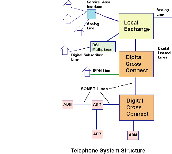
A telephone system has both local and global parts and has the organization shown below:
The center of the system is the Central Exchange (CEX), which is the primary switching location for normal analog telephone lines. However, the telphone system has long used digital technology for long distance and high capacity communications, as evidenced by the Digital Cross Connect (DCC). The DCC's serve local ISDN and leased digital lines,and serve as a point in a global digital network that routes telephone calls world wide over SONET lines. This is obviously a complex system and we won't attempt to discuss it in detail, but the essential points will be discussed below.
Basic Analog and Digital Methods
Analog
Historically, the telphone system used analog lines. Telephones converted sound to an electrical signal and transmitted it directly over the lines. The incoming line was connected to the CEX where the signal was switched to an outgoing line. It was all quite simple. The only characteristic of interest was that the signal was filtered to a maximum of 4000 Hz. This was primarily to avoid transmission problems with higher frequencies that are not necessary for adequate normal voice.
Digital
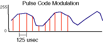
For all of the reasons discussed earlier, the telphone companies decided that digital services were superior to analog in the 1960's. The cost of converting the entire system was too expensive, but they did begin convering the long distance services to digital. The first problem is how to convert an analog signal to a digital form. The process is called, obviously, analog-to-digital or A/D conversion. It is accomplished by sampling the analog signal at some frequency, and at each point, representing the amplitude of the signal as a number. The method used by the telephone system is named Pulse Code Modulation (PCM) and looks like this:
In order to insure that 4000 Hz can be adequately represented, 8000 samples per second are required, or one sample every 125 microseconds (usec). Initially, each sample was a 7 bit sample, but later, 8 bits was used, particularly for data.
-
8000 samples/sec * 8 bits = 64,000 bits per second
So, a single PCM channel provides 64,000 bits of capacity, which is enough to carry one voice channel. Remember, to represent 4000 Hz, you need to sample 8000 times per second (2 samples per cycle).
The "T" Standards The carriers that are used for distance communication have higher capacities, so they bundle multiple channels together into Digital Signaling (DS) carriers.
- DS0 - 64,000 bps, for carrying data
- DS0A - 56,000 bps, for carrying voice
- T1 carrier (DS1)
-
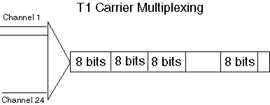
24 PCM channels + 1 control bit = 193 bits * 8000 =
1,544,000 bits/sec = 1.544 Mbps
- T-3 carrier (DS3) - 24 T-1 channels = 37.056 Mbps
but framing information is added so that the total bit rate is 44.736 Mbps. The multiplexing of the channels is done bit-by-bit, so that the 193 bits of each T-1 frame is spread evenly throughout the T-3 frame. - There are also T2 (4 T1's) and T4 (7 T3's) carriers, but they are seldom used.
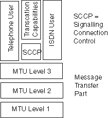
- Signaling System 7 (SS7) - A protocol architecture
stack to support packet network delivery of telecommunication
data. It is designed to handle call setup/teardown, wireless
services, call forwarding, caller id, conference calling, etc.
These DS carriers have been the mainstay of high capacity data communication since the 1970's. Many leased lines are T1 or T3 carriers.
It is also possible to fractionate these carriers and buy only part of a T1 or T3. If you buy one channel, you get 64 kbps and additional capacity comes in 64 kbps chunks.
T carriers use time-division multiplexing with fixed time slots. A T1 releases one frame every 125 usec, and each frame contains 24 channels. So each channel gets 1/24 of the capacity of the carrier and then 125 usec later, it gets 1/24 of the carrier again. Each channel is taking turns by sending one 8-bit word each 125 usec. If a channel is unused during one of the time slots, that space in the frame is wasted.
ISDN
Integrated Services Digital Network is a technology whose time didn't ever quite arrive. In theory, homes would have been connected to the CEX with ISDN lines, which consisted of two 64 kbps channels and one 16 kbps signalling channel. ISDN would have provided digital telephone to homes as well as other digital services, but the number of installations has always been very small .
SONET
A more modern carrier is Synchronous Optical NETwork, which was designed to operate over fiber media at very high data rates - well over 1 Gbps. SONET uses synchronous framing, transmitting frames (are you ready?) 8000 times per second.
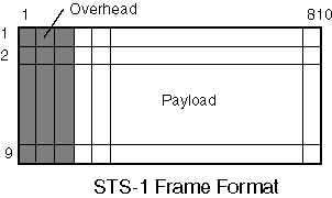
SONET is part of a set of standards called the Synchronous Digital Hierarchy (SDH) which is designed to provide high-speed backbone networks. The basic building block is called synchronous transport signal level 1 (STS-1) and it has the following frame format.
As you can see, each STS-1 frame contains 90 bytes * 9 rows = 810 bytes, with 27 overhead bytes and 783 payload bytes. At 8000 fps, the total capacity is
810 bytes/frame * 8 bits/byte * 8000 frames/sec = 51.84 Mbps
Each byte in the frame represents 64 kbps of capacity at 8000 times per second. SONET uses NRZ encoding of the overhead bytes and to insure timing information is present, the data is xor'ed with a known 127 bit string. This is called scrambling. SONET uses synchronous framing which means that a frame is delivered every 125 usec and each frame is the same length. This eliminates the need to worry about the length or sentinels and speeds up communications.
As with the DS standards, there is a hierarchy of carriers.
| SONET Signal | Optical Signal | Bit Rate |
|---|---|---|
| STS-1 | OC-1 | 51.84 Mbps |
| STS-3 | OC-3 | 155.52 Mbps |
| STS-9 | OC-9 | 466.56 Mbps |
| STS-12 | OC-12 | 622.08 Mbps |
| STS-18 | OC-18 | 933.12 Mbps |
| STS-24 | OC-24 | 1244.16 Mbps |
| STS-36 | OC-36 | 1866.24 Mbps |
| STS-48 | OC-48 | 2488.32 Mbps |
| STS-192 | OC-192 | 8853.28 Mbps |
SONET uses the add-drop multiplexors (ADM) to rapidly add or remove tributary streams. For example, at an ADM, it might add some STS frames to be sent to other locations, while removing traffic destined for the local network. The ADM's are designed to do this without demultiplexing all of the traffic, which is very time consuming. This makes SONET a very efficient carrier for high speed traffic that also allows routing. The multiplexing is done column first within a frame, and the interleaving is byte-by-byte between STS-1 channels.
Modem Technology
Everyone is familiar with modem technology, and it has been a part of computing since the earliest years. Early modems were 110 baud or 10 character per second contraptions that were acoustically connected to telephone lines. Modems have gone through a variety of evolutionary stages. Remember that at all times, the 3000 Hz bandwidth limit acts to limit that speed at which one can transmit.
One standard was known as Bell 103, which is a standard for 1200 baud or 120 character per second models.
- FSK encoding for 300 bps (and 300 baud)
- Originator uses 1070 HZ for 0, 1270 HZ for 1
- Answerer uses 2025 HZ for 0, 2225 HZ for 1
- Bandwidth = 2225 Hz
A more recent standard is called Quadrature Amplitude Modulation. It uses phase-shift keying at 30 degree increments for a total of twelve symbols.
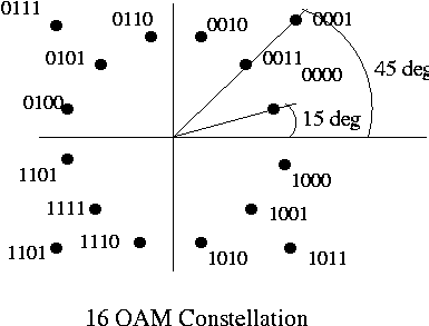
Then, it uses amplitude shift keying as shown on 4 of those symbols to get 16 symbols, so that 4 bits can be sent in each symbol. Bell 209 (V.29) modems use a transmission rate of 2400 baud, for a total of 9600 bps.
This method is known as 16-QAM beacuse it provides 16 signal levels. There are standards for QAM up to 4096-QAM, which would provide 11 bits per baud, but they use a slightly different approach.
Trellis Coding is QAM, but it uses two signals added together and it leaves some signals unused. A constellation is shown below:
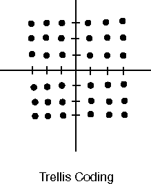
This constellation has 36 different signal levels defined. Rotation around the origin represents different phase angles, and at each angle, different points represent different amplitudes. By creating two waves, one a sine and one a cosine, it is possible to double the number of states, as each wave has both a phase angle and an amplitude.
The problem is that as the number of points in the constellation increases, it is more likely that a small perturbation of the signal will result in an error at the receiver. So Trellis Coding leaves some points unused. Normally, it tries to separate legal signals with some signals that are not legal, so a small signal degradation will result in an illegal signal being received, rather than a legal one. In this manner, it is possible to add error checking to the basic protocol.
Some of the modem standards that use Trellis Coding are:
| Standard | QAM Method | Bit Rate |
|---|---|---|
| V.32 | 32-QAM Trellis | 9600 bps |
| V.32bis | 64-QAM Trellis | 14,400 bps |
| V.33 | 128-QAM Trellis | 14,400 bps |
| V.34 | 4096-QAM | 28,800 bps |
56kbps Modems
56 kbps modems don't really exist, per se. The maximum bit rate on a telephone line is somewhere in the neighborhood of 33,600 bps. However, specifications such as V.90 take advantage of the fact that on the downstream side, it is possible to go faster since it isn't necessary to perform the PCM conversion on digital lines. This allows an upstream rate of 33.6 kbps and a downstream rate of 56 kbps.Digital Subscriber Lines
Digital Subscriber Line or DSL is one of the hot technologies of recent years. As the demands for higher capacities began to extend to homes and small businesses, there was a need for a low cost carrier that would support speeds greater than modems (56 kbps). This has been accomplished with Digital Subscriber Lines or (DSL). What is particularly attractive is that DSL is designed to run over existing copper wires, and at rates of up to 55 Mbps (currently).
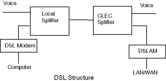
It is really a simply application of FDM, where the bandwidth above 4000 Hz on your telephone line is used to carry data. The basic layout is:
At your home, the voice traffic is transmitted as usual in the 0-4000 Hz band, and your data traffic is converted to an analog form and transmitted in higher bands. At the switching office for your DSL supplier, the two signals are split, with your voice traffic heading off to your local telephone company and the data going to your suppliers network.
The important issue is how to distribute the data in the available bandwidth. If all of the data is placed in one band, there would be a tendancy to make the bandwidth as high as possible to maximize data rates (e.g a single 500 Mhz band), but that could create a problem. If you make the band wide enough to get maximum advantage from the newest local loop technology, you would eliminate a huge customer base that has older telephone lines. On the other hand, if you try to accomodate the worst lines, you will have a technology that isn't very exciting. So DSL was made to be quite modular. The bandwidth from 4000 Hz to 1 GHz is divided into 4000 Hz bands. These 4000 Hz channels can carry data concurrently, giving a total data rate that is some multiple of the capacity of any single channel. The channels can be used in a variety of ways to carry data so that a number of different standards have been developed to provide particular types of service. Some are symmetrical, with the same upstream and downstream rates, while others are not, and there is a speed to handle virtually any need.
There is a family of DSL standards, each of which is designed to serve some particular need. The following table shows some of possible services. Note that DSL doesn't necessarily have to be the same speed in both directions.
|
Name
|
Downstream Rate
|
Upstream Rate
|
Distance/Media
|
Description
|
| Digital Subscriber Line | 160 Kbps | 160 Kbps | 18,000 feet | Basic DSL Interface |
|
IDSL - ISDN Digital Subscriber Line |
128 Kbps | 128 Kbps | 18,000 feet on 24 gauge wire | Similar to the ISDN BRI service but data only (no voice on the same line) |
| DSL Lite (same as G.Lite) | 1.544 Mbps to 6 Mbps | 1.544 Mbps to 6 Mbps | 8,000 feet on 24 gauge wire | Splitterless DSL without the truck roll |
| HDSL - High bit-rate Digital Subscriber Line |
1.544 Mbps duplex on two twisted-pair lines; 2.048 Mbps duplex on three twisted-pair lines |
1.544 Mbps duplex on two twisted-pair lines; 2.048 Mbps duplex on three twisted-pair lines |
12,000 feet on 24 gauge wire | T1/E1 service between server and phone company or within a company; |
|
SDSL - Single-line DSL |
1.544 Mbps; 2.048 Mbps (Europe) |
1.544 Mbps
2.048 Mbps (Europe) |
12,000 feet on 24 gauge wire | Same as for HDSL but requiring only one line of twisted-pair |
| ADSL - Asymmetric Digital Subscriber Line | 16 to 640 Kbps | 1.544 to 6.1 Mbps |
1.544 Mbps at 18,000 feet; 2.048 Mbps at 16,000 feet; 6.312 Mpbs at 12,000 feet; 8.448 Mbps at 9,000 feet |
Used for Internet and Web access, motion video, video on demand, remote LAN access |
|
VDSL - Very high Digital Subscriber Line |
12.9 to 52.8 Mbps downstream; | 1.5 to 2.3 Mbps upstream; |
,500 feet at 12.96 Mbps; 3,000 feet at 25.82 Mbps; 1,000 feet at 51.84 Mbps |
ATM networks; |
Bit rates above 1.5 Mbps typically require media that is better than your average telephone line, usually twisted pair, which is becoming the standard for new telephone installations. Also, xDSL has some relatively severe distance limitations, with the maximum distance from the DLS multiplexor being about 18,000 feet (some lower speed versions are allowing up to 30,000 feet).
Regular telephone service is carried on the lower 4000 Hz channel, and the high speed digital traffic is encoded up to 1 Ghz, depending on the DSL version. The bandwidth above 4000 Hz is divided into 4000 Hz bands, each of which is used to carry some part of the signal. For example, ADSL encodes the upstream data on up to 25 channels (100,000 Hz). Each channel uses 15 bits/baud encoding so that 60,000 bps can be carried. 25 times 60,000 bps produces 1.5 Mbps. Similarly, the downstream side can occupy up to 200 channels (800,000 Hz) and produce up to 60,000 bps * 200 = 12,000,000 bps.
The encoding method is similar to Quadrature Amplitude Modulation (discussed above) and is called Discrete Multitone Technique (DMT). HDSL uses a different encoding method called 2B1Q which has 4 different voltage levels, so it is a form of ASK, combined with DMT and FDM.
