Introduction
While it is common to not differentiate between an Ethernet and an IEEE 802.3 network, there are actually differences between the standards. We won't worry about them here and will call either type an Ethernet even though the most widely used type is IEEE 802.3.An Ethernet is a TDM network that uses contention to divide the capacity between the nodes. If a node has nothing to send, it simply does nothing; if a node has something to send, it competes with all other nodes trying to send to get the right to send its message. The advantage is that no centralized control is required for an Ethernet and the access protocol is very simple, making it easy to implement and easily scalable; the disadvantage is that the contention can consume quite a bit of capacity, particularly under heavy loads.
CSMA or Carrier Sense Multiple Access indicates that an Ethernet network allows multiple nodes to access a network simultaneously as long as they all sense or listen to the carrier to see if it is busy before sending. While this seems trivial, there are networks where that is not necessary. In addition, the CSMA/CD method used by Ethernet adds Collision Detection, which requires that a node listen for collisions and recognize that a message has been destroyed by a collision. Again, this seems obvious, but some contention networks don't do this.
The five properties of the physical layer for an Ethernet depend on what type we are discussing. The access control, frame format and error management do not change, but the physical layer methods change dramatically:
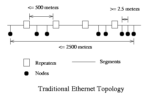
Signaling method - All methods use Manchester encoding using +0.85 volts and -0.85 volts for zero and one. Physical Media - Thick Lan uses 10Base5 media, which is a rather large and bulky coaxial cable; 500 m maximum segment length; 2500 m maximum network length; maximum of 100 nodes per segment. ThinLan uses 10Base2 media, which is RG-58 coaxial cable; 200 meter maximum segment length; 1000 meter total length maximum and a maximum of 30 nodes per segment.
The simplest topology is:
Access Method - CSMA/CD using 1-persistence and binary exponential backoff for collision resolution. To say this another way:
- Listen to see if the network is busy. Wait until its not busy - this is 1-persistence.
- Try to send; if no collision is detected in the first 51.2 µs there shouldn't be a collision, but listen anyway.
- If you have a collision as evidenced by hearing gibberish on the network or sensing a collision detect signal from some other node, execute the binary exponential backoff algorithm. To whit, after the nth (n = 1-10) consecutive collision trying to send a message, pick a random number between 0 and 2n-1 and wait that many 51.2 microsecond slots before returning to step 1.
- Error Control - Each frame contains a 32-bit CRC that is used to detect errors, but the MAC layer of Ethernet does not do any responding on its own, leaving that for upper layers.
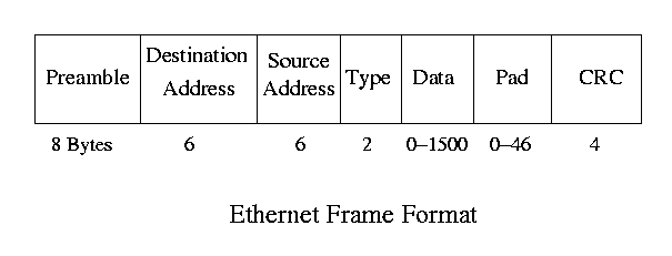
Frame Format -
- The preamble is a sequence of alternating zeros and ones used to get the receiver and sender synchronized.
- The addresses are standard 48-bit Ethernet addresses which are unique to every Ethernet device.
- The type indicates the protocol which needs to get the message on the receiving end; it is used to multiplex protocols over the Ethernet physical layer. For example, if the IP protocol sends a message, it puts the IP protocol type (16) in the type field to be used to direct the message to the IP layer on the receiving end.
- The pad insures the message is at least 512 bits long.
- The CRC is the 32-bit CRC for frame checking.
Collision Detection
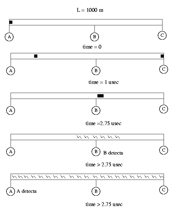
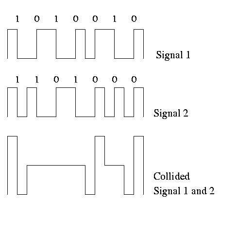
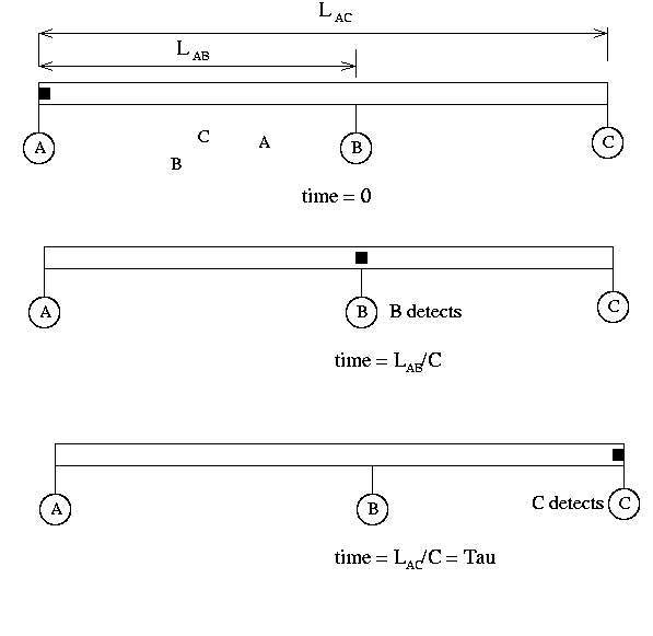
One of the most important concepts to get from this discussion is the collision detection and resolution methods that are necessary in Ethernet. The following diagram shows what happens when one node A, sends a message at time 0 that eventually collides with a message sent by node C at time 1 µs. The collision happens at time 2.75 µs and it first seen by node B. Node B notices that the data on the cable is outside of the standard signal requirements and interprets that as a collision. An example of what happens to the signal is shown below.
While the collided signal would continue to propogate to all parts of the network cable, B will take no chances on any misinterpretation. When a node recognizes a collision, it generates a collision detect signal which is a burst of alternating zeros and ones at an amplitude greater than the normal signal power. In this way, all stations will be certain to see the collision.
It is most important for A and C to know that the frames were destroyed as they will have to be resent. To insure this happens, both A and C must be listening to the cable when the collision propogates to their location. The maximum time this can take is the time it takes for this to happen is called the 2-tau time period and is the round-trip time between the sending station and the farthest station on the network. This is demonstrated in the diagram below:
Fast Ethernet
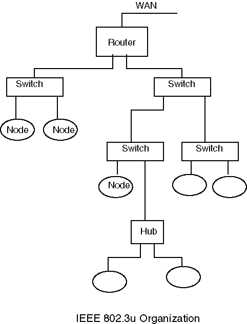
The book has a good description of standard Ethernet, but it doesn't have much to say about the newer Ethernet standards, Fast Ethernet and Gigabit Ethernet. They generally go by these monikers even though they are officially known as IEEE 802.3u and IEEE 802.3z/IEEE 802.3ab. While the bit rates and the signaling methods vary between these systems, the major difference between them and standard Ethernet is their architecture. Both of these systems are essentially star topology networks rather than bus networks, but with access and message distribution strategies that mimic those of Ethernet. In many ways, they are completely different networks, but the Ethernet name was seen as a good selling point.
The architecure is:
This is a cascading star network, where the switches act as controllers for all of the connected nodes. If a node transmits a frame, it is seen only by the switch, which looks at the destination address and forwards it only to the recipient, not to all nodes. The switch can buffer the incoming frames, so nodes can transmit simultaneously and the only contention would be simultaneous deliveries to the same node. It is still possible to broadcast a message to all nodes on its network. The switches recognize that any address not local to the switch and send that traffic back up the tree. The hubs connect multiple nodes like a switch but have none of the smarts; all incoming messages from any source are transmitted to all connections.
The nodes see virtually no difference in terms of activity; the same access protocol and signaling methods are used. The big difference is the use of a 100 Mbps bit rate, rather than 10 Mbps. In order to accomodate this, the distance had to be reduced, so 100 meters was chosen, and since the distance was shorter, a medium with reduced capabilities was acceptable. The most common media is Category 5 Unshielded Twisted Pair (Cat 5 UTP) (100Base-TX), but there are also standards for fiber (100Base-FX) and one that uses two links between the switch and node (100Base-X) which allows concurrent transmission and reception or full duplex operation.
Utilization
Determining the utilization of an Ethernet network is difficult primarily because of the binary exponential backoff part of the access algorithm. However, you can get some rough estimates by determining average case behavior of a network. If a node has a message to send, it will, on average, try and fail a certain number of times. Each time it fails, it will wait some average number of time slots. Finally, it will send its average length message. This activity spread over all the nodes on the network provides an average behavior that represents the utilization. One assumption that is often made is that time on an Ethernet is divided into slots when no message is being sent. A slot is just the time necessary to send the minimum frame of 512 bits or 51.2 µs. If a station sends and there is a collision, it will waste one slot, more or less.Some definitions from before:
-
Let D = the network length, L be the message length, R is the data rate
and V is the propagation rate.
Let a be the ratio of propagation delay to message transmit time = (D/V)/(L/R) = DR/LV.
Let &tau be signal propogation time, &tau = D/V.
Let A be the probability that a node acquires the channel and sends a
message.
There are three cases for each slot; no node sends, one node sends, or more than one node sends. In the first case, the slot is wasted; in the second the slot is used (and sufficient slots to send the message); in the third, there is a collision and the backoff process takes place. Only the second produces throughput of data and the probability of that happening is calculated from the binomial distribution which describes the probability of n out of N nodes sending if the probability of sending is p for each node:
The probability of exactly one of N stations sending, where the probability of a station sending is equal over all stations so that p = 1/N is:
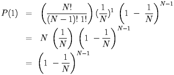 |
This is A, the probability that in any given slot, the channel is acquired by one node that sends successfully. As N gets large, A approaches 1/e-1 = 0.368.
The next thing we need to know is how much time is used in the event of a collision. The binary exponential backoff algorithm makes this difficult, but we can simplify by assuming that we know something about the average case behavior. What we really need to know is the probability that we have a certain number of consecutive slots that involve a collision and we already have that. If no station sends, a slot is lost and we already know the probability that one station successfully sends. Then, the expected length of a contention period can be calculated from the geometric distribution. If a process has a probability of success of A, then the expected number of trials before a success is 1/A. The expected number of failures before succeeding is 1/A - 1.
We can calculate the utilization, U = Data Transport Time/Total Time, so,
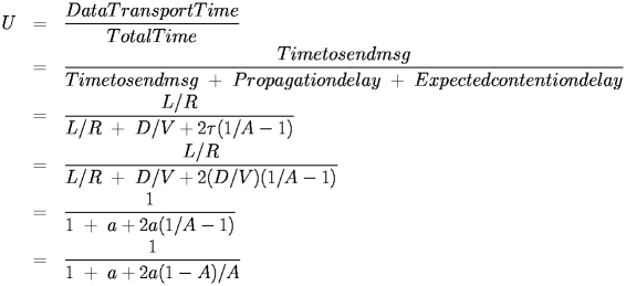 |
The utilization can be understood by observing that we have effectively determined that for a successful send, there is a cost of (1-A)/A slots which includes the probability of zero sends and wasted contentions slots. The length of a contention slot is always the same, but the length of the transmit time may vary, so a is not a constant. In some formulations, the above equation is does not have the second term, which ignores the propogation delay in sending the message. This is acceptable in that this term is likely to be small, but it does exist.
There is also the issue of efficacy. IEEE 802.3/Ethernet frames can have very high overhead. There are at least 28 bytes of framing information and that could be up to 63 bytes if the data block is not long enough. This has to be taken into account by modifying the utilization equations to reflect a smaller amount of data or data time. For example, if the frame length is 1024 bits, but 28 bytes are framing, the actual transmit time for the data is 800/107 seconds, not 1024/107 seconds. If M is the number of data bits in the equation, the modified equation is:
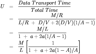 |
With any model, you should consider that assumptions and simplifications that are made. First, this model assumes that all messages are 512 bits long, which isn't necessarily reasonable. However, in practice it is often close as most network messages are relatively short. However, it is not true that all of the bits in a message are data bits. Analyzing a situation should take this into account. This model uses a very simplisitic view of the contention algorithm and it doesn't consider that network traffic is seldom homogenous across the network, so the assumption of equal probabilities of sending is suspect. Nevertheless, it is simple to analyze and reasonably accurate so we can use it. Interestingly, if you allow N to get very large, the formula above reaches the following limit:
 |
For example, if a network has 10 nodes and each message has 512 data bits and 208 overhead bits:
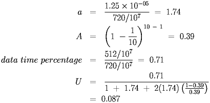 |
The numerator becomes (L-O)/R, where O is the length of the overhead in the frame, and the utilization decreases.
Throughput is the amount of data transmitted per unit time, which would be the probability of a successful send times the efficiency of that send, times the data rate of the network, or:
 |
For the previous example, this would be:
 |
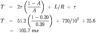
Also of interest is the response time of the nodes to a request. If a user submits a request for some network service, what is the expected response time of the node to sending the request. We need to know the expected wait time that a node would endure. We already know the expected number of failures is 1/A-1 and the length of both the contention slot and the actual send, so the response time for the previous example is:
 |
