Introduction
The discussion of token rings in the book is fairly complete, so all I will offer here are a few additional points. Token rings were some of the first local area networks, predating Ethernet by several years. They have been found to be very reliable and actually more robust and higher performance than Ethernets. So why aren't they more common you ask? Token rings are somewhat more difficult to implement and manage, but the real problem was that proponents didn't respond to the changing conditions precipated by Ethernet networks, particularly, lower costs.It is important to note that the ring topology is a sequence of point to point links, not a continuous piece of cable that all the nodes connect to. So the nodes are an integral part of the communication process, not simple users of the medium.
Properties
Token rings come in many flavors, so to discuss the properties of a token ring we have to narrow the field to a couple, which will be IEEE 802.5 and FDDI (Fiber Distributed Data Interface). All token rings are similar, differing only slightly in the five properties.IEEE 802.5
Signaling method - Differential Manchester encoding using +3.3 volts and -3.3 at 4Mbps, 16 Mbps or 100 Mbps (fiber only). Physical Media UTP/STP/fiber with maximum cable lengths between stations of 150 m/375m/2 km and a maximum number of stations on a ring segment of 250 . Coaxial cable can also be used to replace STP. Access Method - Token-passing as described below.
- Error Control - Each frame contains a 32-bit CRC (called a frame check sequence that is used to detect errors, and check bits to be set by receivers to indicate frame status.
- Frame Format - The frame format is:
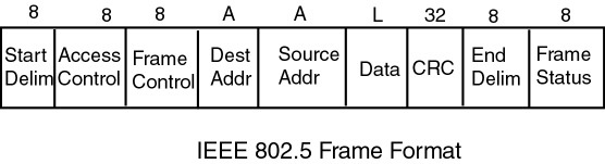
- The start and end delimiters use special symbols that are allowed in Differential Manchester encoding but do not translate as zeros or ones. An example of sentinel framing.
- The access control byte has fields that allow the stations to set and honor priorities on messages.
- The frame control byte contains among other things the token bit. A single bit that indicates if the frame contains data or is the token.
- Addresses can be 16 bits or 48 bits.
- Maximum frame length is 4550 bytes for 4 Mbps rings and 18,2000 bytes for faster networks.
- The frame status has two bits: Address recognized and frame-copied.
Token Ring Access Control
The access control method for an IEEE 802.5 token ring is a complicated process that involves priorities, reservations, lost tokens and many other things, all of which are not that important in terms of understanding the fundamental access method. Basically it works like this:- A message arrives at a node, one bit at a time from the cable. The station shifts the message through its shift register, first the start delimiter, then the access control byte and finally the frame control byte. It adds bit delays as specified in its configuration.
- If the token bit is not set, indicating that the message has data in it, the node looks at the destination address when it passes through but does not try to send any of its own data.
- If the address its its own, it copies the data from the message (also transmitting it on the output side) and when the frame status byte goes through, sets the bits appropriately; if it recognized its address, set the Address Recognized bit and if the message was copied, set the Message Copied bit. It is possible for a station to not copy the message if it lacks buffer space.
- If the token bit is set, the token can be siezed or captured if the station has something to send. It simply changes the token bit to zero as it is sent, and then fills the address, data and CRC fields for its message.
- When bits begin coming in on the input side, they are removed from the network until the frame status is reached and the bits are checked to see if the message was received.
- Generate a new message with the token bit set and no data if there are no other messages buffered or the maximum holding time has been reached. Otherwise, put another message in it.
The token holding time is a time parameter that specifies how long a node can hold the token and continue to send before giving it up.
Performance
The utilization of a token ring it relatively easy to determine. In addition to sending data, the nodes have to send frame overhead and they have to pass the token until a node needs to send. If the network data rate is 16 Mbps and the token is 24 bits, each time the token passes between nodes it takes:

If the probability of a station sending is 0.10, 90% of the time it will pass the token, and 10% of the time is will send a message. If messages are 1024 bits long and the frame overhead is 128 bits, each send takes:

and (128/1024) 12.5% of that time is frame overhead.
So in a round of 20 stations, you would expect that 0.10 * 20 = 2 nodes to send and 0.90 * 20 = 18 would simply pass the token. The total time for a round is:

Note that you have to count the token passing time all 20 times because the stations that send data also pass the token. Since only 87.5% of the message time is actually spend sending data, the utilization is:

This example ignores two issues; one is the possibility of bit delays added at each station, which would be added to the denominator; the second is the propagation delay in the cable which would be the length of the cable divided by the propogation rate of the signal.
If you want to expand this into a general equation for computing the utilization, you need to determine a time frame that would allow you to compare varying values of length, bit delays, number of nodes and so on. Using the following terms:
- N = the number of nodes on the ring
- P = the probability that a station sends
- D = length of the ring
- B = the number of bit delays per station
- R = bit rate
- L = message length
- M = data bits in the message (e.g. header length = L-M)
- T = token length
- V = signal propagation rate
One possible way to approach this is to use the capacity of the network as given by R. If R is 1 Mbps, then we can determine the amount of data produced by the network in one second and compare it to 1 Mbit to determine the utilization. Suppose we have a ring with the following properties:
- N = 10
- P = 0.20
- D = 4000 m
- B = 8
- R = 1 Mbps
- L = 12500 bits
- M = 12244 bits
- T = 32 bits
- V = 2x10⁸ m/s

The delays during the cycle would include the bit delays in each station and the propogation delay. Each message has to propogate around the ring, plus the token makes one full trip. Together these determine the network latency which is:

These two added together represent the total cycle time for the token, which is:

With this cycle time, you would get:

The amount of data sent per cycle is:

So in 397.93 cycles or one second, you would expect to send:

So the utilization is:
If you are looking for a formula, collect the terms above and get:

You can try this formula for the example above for a few cases by modifying the parameters to see what you get. The following shows the change in utilization as the message length increases.
Message Length in bits Utilization 1000 0.61 5000 0.91 10000 0.95 15000 0.96 20000 0.97
It is simple to try it for other parameter changes, such as N, R and P.
It would be nice to have a formula that we could compare to the Ethernet worst case performance, and we can do that with a little modeling sleight-of-hand. First, let the number of message bits fill the frame so that M=L, and then ignore the token-passing and delay bits on the grounds that they are insignificant in comparison to the message transmit term. Finally, divide through by L/R as we did before to get:
 |
If you compare this to the formula for an IEEE 802.3 network:
 |
You can see that as the probability of a node sending grows large (A gets large and P gets large), the utilization for a token ring network will get higher, while it will reach a maximum and remain there for an IEEE 802.3. Of course, we know that utilization for an IEEE 802.3 will actually decrease due to the difficulties with backlogging of requests while a token ring doesn't suffer from this problem at all. When P is 1.0, the token ring is performing at its absolute best with respect to utilization. It actually approaches a theoretical maximum at 1/(1+a). That doesn't mean that the users are happy, because throughput is also limited and response time decreases.
In general, a token ring network has very good high load performance and it is much better than an Ethernet-type of network. But it has the disadvantage of higher administrative overhead and it is somewhat less scalable.
FDDI
Fiber Distributed Data Interface has been around for quite a long time and is similar, to IEEE 802.5. It is designed for a fiber medium, but also allows a coaxial cable and twisted pair implementations. It was designed for large implementations of up to several hunder kilometers, so it can theoretically be used for LAN, WAN or MAN configurations.It's access algorithm is quite a bit more complicated than basic IEEE 802.5 and won't be discussed here. However, it is basically the same procedure, but with several added features.