Introduction
The discussion of 802.11b in the book is reasonably complete so this will be mostly clarifications and extensions. There are many different types of wireless networks that differ primarily in the frequency band used, the range of the signals and the access methods used. As interesting as all this might be, we will limit ourselves to one specific implementation. There are several IEEE wireless network standards, including IEEE 802.11 standards for local area networks, IEEE 802.15 for personal networks, such as Bluetooth and IEEE 802.16 for broadband wireless access. In the IEEE 802.11 standard there are IEEE 802.11b and 802.11a, which differ only in the frequency band that they use and speed, and IEEE 802.11g which is a faster 802.11b, but may never actually see the light of day.The fundamental property of a wireless network is that it uses unguided media, which means that it operates in a designated frequency band. Some bands are open, and anyone can build a device that uses that band as long as they obey some simple rules. Other bands are licensed and can be used only by devices that are licensed by licensors as designated by the FCC. With this thought in mind, lets consider how such a network might work.
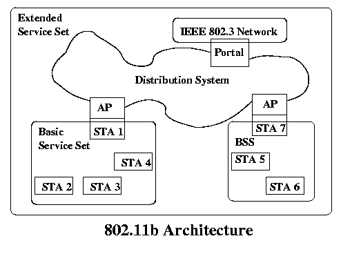
The architecture of an IEEE 802.11b network looks like this:
A Basic Service Set (BSS) is an area where all of the stations are within wireless range of only stations in the same BSS. This does include cases where a station belongs to more than 1 BSS, so they can overlap. One or more of these stations can be access points (AP's), which have access to a Distribution System (DS). Several BSS's connected together by a DS form an Extended Service Set (ESS). Finally, a Portal can be used to connect a distribution system to another type of network. This can be very simple in the case of an AP that also serves as a Portal, so that a single BSS can be connected to a Fast Ethernet network as shown.
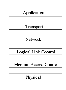
The IEEE 802 protocol stack is continued with the 802.11 protocol.

The Logical Link Control Layer (LLC) is concerned with the transmission of data between endpoints where no switching or routing is involved and the detection of collisions and signals, and the Medium Access Control Layer (MAC) is concerned with functions that involve accessing the data channel and transmission medium and for the actual transmission of the data. In the case of 802.11b, the LLC and MAC layers have specific functions. The entire scope is beyond a simple discussion, but there are five signalling methods defined and two different service types (contention-free and contended service).
Properties
- Signaling method -There are two incompatible encoding methods used - Frequency Hopping Spread Spectrum and Direct Sequency Spread Spectrum. These are discussed below.
Physical Media - the unlicensed band from 2.4 to 2.483 GHz which is commonly known as the ISM band. This band is quite busy with a variety of different wireless systems operating here, so you would expect quite a bit of interference, particularly in highly industrialized areas. Power is limited to 4 watts, which limits distance to possibly 1000 feet line of sight and probably less than 100 meters indoors. Access Method - Distributed Foundation Wireless Medium Access Control Layer is the official name of the Medium Access Control Layer and it is discussed below.
- Error Control - Each frame contains a 32-bit CRC.
- Frame Format -

- Frame Control - Indicates the type of frame and provides control information. It has the following format with sizes in bits:

- Duration/Connection ID - Indicates the duration of a message in usec or in some cases a connection identifier.
- The 4 addresses are discussed below.
- Sequence Control - A 4-bit fragment number subfield and a 12 bit message sequence number
- Payload is the data to send up to 2312 bytes.
Access Control
The access control algorithm has a number of variations, but the two primary modes are infrastructure and ad hoc. Infrastructure is used when an access point is used for communication and ad hoc is used when two wireless stations communicate without using an access point. We will discuss the infrastructure operation only, although the access algorithms are virtually identical.When a wireless node sends a message, it can be intended for another node in its BSS or for a node in another BSS. We won't consider the problem of accessing nodes through a portal. If the node is in its own BSS, it can send the message directly. This only requires two addresses. If the node is in another BSS, it has to send the message to its access point, which has to forward it to the access point for the destination BSS and then finally, that access point forwards it to the destination. This requires four addresses as described in the following table, which shows the relationship between the ToDS and FromDS bits and the four addresses available in the frame.
ToDS and FromDS are used as shown below to specify which addresses are valid. The bits and the address can change as a message makes journeys from the source to the destination, possibly through intermediate access points.
0 0 Dest Node Src Node NA NA 0 1 Dest Node Src AP Src Node NA 1 0 Dest AP Src. Station Dest Station NA 1 1 Dest AP Src AP Dest Station Src Station
Station to station in a BSS 0 0 AP to station in a BSS 0 1 Station to AP 1 0 AP to AP 1 1
For example, suppose you have two BSS's; BSS1 has an AP1 and a station S1 in it; BSS2 has AP2 and a station S2 as a member. If A sends a message to B, the progress of the message and the use of the frame control information is:
S1 to AP1 1 0 AP1 S1 S2 NA AP1 to AP2 1 1 AP2 AP1 S2 S1 AP2 to S2 0 1 S2 AP2 S1 NA
As you can see, at each stage, the control bits specify the use of the fields and they are filled as necessary. The first two address fields are immediate address fields - who is sending and receiving this message now, while the latter two are used to hold the data that may be needed at a later time for delivery.
Every 802.11b device has a unique 48-bit address that is assigned at the time of manufacture. The AP's learn the addresses of the nodes in their BSS, and often, the other stations do as well, depending on their operational mode. The AP's exchange information as necessary to manage the routing function, but that is still relatively limited in most products. As time goes on, the access points will become more capable and powerful if past history means anything.
Their are three frame types (based on the Frame Type field); Management, Control and Data. A subset of these is shown below:
Mgmt(00) 0000 Association Request Mgmt(00) 0001 Association Response Mgmt(00) 0010 Reassociation Request Mgmt(00) 0011 Reassociation Response Mgmt(00) 0100 Probe Request Mgmt(00) 0101 Probe Response Mgmt(00) 1000 Beacon Mgmt(00) 1011 Authentication Control(01) 1011 Request to Send Control(01) 1100 Clear to Send Control(01) 1101 Acknowledgement Data (10) 0000 Data
The management frames are concerned with the formation of BSS's:
- Association- sent by a station to an AP to join a BSS
- Reassociation - sent by a station to an AP when attempting to change its BSS. It allows the new AP to negotiate with the old AP for forwarding of data frames.
- Probe - sent by a station to obtain informatin from another station or AP
- Beacon - sent periodically by an AP to allow stations to locate and identify a BSS
- Authentication - sent by a station to another station or AP to authenticate using the Wired Equivalent Protocol (WEP)
The control frames are concerned with the control of communication services between stations:
- Request to Send (RTS) - Sent by a station to alert a potential destination and all other stations that it intends to send a data frame to that destination.
- Clear to Send (CTS) - Sent by a destination to the source of an RTS.
- Acknowledgement - A station uses this to acknowledge receipt of a message.
The Access Algorithm
In deciding the access algorithm to use for a distributed system, you could consider any method that we have discussed, but each has its disadvantages. Obviously a network designed to handle mobile devices would have severe management problems with any type or round robin or token-passing system, so some form of contention clearly seems best. You might ask - "why not just use CSMA/CD" for the access algorithm. There are several issues that make that a poor solution. For one, in a BSS, it is likely that there will be some stations that can't hear other stations (in the sense that they can't receive their signal). So their signals could be involved in a collision with a station that they don't know is there, and it is possible that they won't even be able to detect the collision, so carrier sense and collision detection are of limited use. This is called the hidden node problem. Another problem is when two nodes can hear each other but are sending to nodes that are out of range of each other so that they can legitimately transmit simultaneously, but don't because they hear each other. For that reason, the access algorithm uses contention in the sense that any station that wants to send can attempt to get control of the media, but the right to send is controlled by the receiver. This method is called Multiple Access with Collision Avoidance or MACA. It is also called CSMA/CA - CSMA with collision avoidance. There are actually three algorithms in use for 802.11b; one uses polling where the access point polls the nodes to see if they want to send; another allows the nodes to send whenever they feel the urge, and a collision or any other problem is indicated by not receiving an ACK from the receiver; the final algorithm as discussed here is similar to the preceding one, except that it includes a process for getting control of the network so that collisions are avoided.This algorithm depends on a number of different time intervals that help the nodes coordinate their activities. They vary depending on the encoding method (see below) used and they are:
|
Space
|
Description
|
DSSS Length | FHSS Length |
| Slot Time | A basic unit of measurement | 20 us | 50 us |
| Short IFS (SIFS) | The period between the completion of a packet transmission and the start of the next possible frame. | 10 | 28 |
| Point Coordination IFS (PIFS) | SIFS plus one slot time. Used in the polling protocol. | 30 | 78 |
| Distributed IFS (DIFS) | PIFS plus one slot time. If a node finds the medium clear for this length of time, it can send. | 50 | 128 |
| Extended IFS (EIFS) | A longer period of time only used when a node receives a frame with an error equal to as much as a couple of milliseconds. | - | - |
The algorithm is:
Assume that station A wants to send to B:
- A listens to the carrier for a signal (knowing that it might not hear everything) and if it doesn't detect a signal for a length of DIFS it can send.
- If it is busy, A monitors the signal until is is free (1-persistence) and then waits one DIFS.
- If the medium remains idle, it backs off a random number of slots and then returns to step 1. If it remains idle it sends, otherwise it cycles through the backoff process again.
- If a station is in the wait cycle and hears another station transmit, it stops the countdown and starts it again when the network is idle.
- A sends a Request-to-Send (RTS) to B that includes the frame length.
- B sends a Clear-to-Send (CTS) to A which echoes the frame length.
- All stations hearing the exchange refrain from sending for the necessary time based on the frame length.
- A sends the data frame.
- B sends an Acknowledgement (ACK) to A (and all others listening).
- If an RTS is involved in a collision, the receivers do not return a CTS (because they probably can't figure out what was in the message anyway). The stations involved in the collision time out waiting and then use binary exponential backoff to select a time period to wait before trying again.
- If a frame is corrupted by noise (possibly by devices that are not part of the 802.11b network), no ACK is sent and A will start over (but no binary exponential backoff is used as there was no collision). There is no guarantee that the ACK will be delivered, so it is possible that a delivered message will be delivered again.
In the above, B could be another station (in ad hoc mode) or it could be an access point (in infrastructure mode).
The other issue is how the stations and AP's know about each other. Mobile stations are known as roaming stations. The interaction between the roaming stations and the AP's is accomplished with the management frames:
- AP's regularly send Beacon frames (10-100 times per second) so that other AP's know about each other and stations know about AP's that they can communicate with. The data sent in a Beacon frame allows stations to send to the AP.
- Stations send Probe frames asking for information about access points in range and access points respond with Probe Response Frames providing information about the access point.
- Roaming stations send Association Request Frames indicating their desire to join a BSS and wait for the access point to respond with an Association Response Frame.
- A weakened signal will result in a new round of probing for an available access point.
- Authentication is required if the AP is configured to use the Wired Equivalent Protocol (WEP) using the Authentication frame.
The Beacon frames contain valuable information about the access points, including
Signal Encoding using Spread Spectrum
The problem with 802.11b and most wireless systems is that there is quite a bit of traffic in the frequency band being used and that interferes and can result in data being lost. Spread spectrum is the name for several methods that can be used to resolve this problem and the name is based on the way that they utilize the available bandwidth.Spread spectrum operates by using a relatively narrow channel to carry data which is analog encoded (usually FSK or PSK). However, to avoid jamming or to improve reception, the signal is spread over a larger band. These techniques may be used to make signal more reliable, but also to arbitrate the use of a channel by many simultaneous users. Two methods for doing this are Frequency Hopping (FHSS) or Direct Sequence (DSSS) Spread Spectrum.
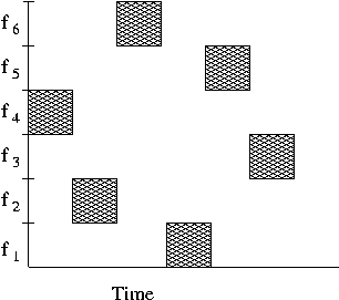
Frequency hopping is based on reducing the likelihood of a collision. If all or even several stations transmit at the same frequency, the likelihood of a collision increases significantly. Frequency hopping systems change the frequencies that are used to transmit so that stations avoid this problem. The available 83.4 MHz band is divided into 79 1 Mhz channels (with the remainder used for control signals). When a station transmits, it uses a particular frequency, but that frequency changes on a regular basis. For example, in the U.S., the IEEE 802.11b FHSS standards require that the frequency change at least 2.5 times per second. All members of a BSS are synchronized to change frequencies at the same time and to the same frequencies, so there is no problem with signal reception. The sequence of frequencies to use is deliberately chosen to appear as a random sequence as shown below.
Since a single station doesn't use the entire bandwidth, collisions occur only if two stations use the same frequency, so it is easier to support multiple uses of the bandwidth.
The encoding for the FHSS method uses 500 k baud in the 1 MHz bands with either 2 or 4-bit FSK encoding for bit rates of 1 or 2 Mbps.
The other method used by 802.11b is Direct Sequence Spread Spectrum (DSSS) which takes a completely different approach. Instead of trying to avoid a collision on a band, it attempts to survive the collision by adding enough information to the signal to allow it to be extracted from the noisy channel. This isn't always possible, especially if there is some non 802.11b high power device close by that effectively wipes the signal out.
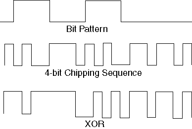
The idea is to take the signal and encode it with a chipping sequence. This means that the NRZ signal is xor'ed with a bit pattern that effectively converts each bit into a sequence of bits that are much shorter in duration. Obviously this increases the frequency requirments of the signal, hence the spread spectrum name. So how does this improve the message reliability? Since the receiver knows the chipping sequence, it can match the incoming signal with the chipping signal looking at the correlation. If it finds a high correlation it has probably found a signal that belongs to some IEEE 802.11b device. For example, the following example uses a four-bit chipping sequence to encode a string of bits.
802.11b uses the following DSSS properties:
- 802.11 generates bits at 1 Mbps and uses an 11-bit chipping sequence standard, so the channels must be at least 11 MHz wide.
- The two chipping keys are used in 802.11b depending on the data rate. At 1 and 2 Mbps the 11-bit Barker sequence (+-++-+++---, where + is +1 and - is -1), so each data one becomes +-++-+++--- and each zero becomes -+--+---+++. At the 5.5 and 11 Mbps data rates, the 8 bit CCK (Complementary Code Keying sequence is used.
- In the U.S., channels are 13 Mbps wide and spaced 5 MHz apart.
- PSK encoding is used. There are four systems
Data Rate Sequence Len Baud Rate Bits/Symbol 1 Mbps 11 1 M 1 2 Mbps 11 1M 2 5.5 Mbps 8 1.375 M 4 11 Mbps 8 1.375 M 8
- Nodes can dynamically change the data rate to meet changing conditions, such as signal weakness or errors.
- The correlated data/enoding signal can be recovered from the signal by removing the uncorrelated noise component.
- DSSS has higher bandwidth capability but is more costly.
- Infrared standard uses diffused IR, with a range of about 10m.


