This week you get to do a "Celebrity Routing Death Match". You will use OpNet to simulate a small internetwork that uses RIP to distribute routing information vs. one that uses OSPF.
Boot your machine in Windows and start OpNet. You're starting with a clean slate; feel free to name the project anything you want and set up the network topology the way you like. You will be setting up an internetwork - when you create the project, set the network scale to be campus-wide and select the internet_toolbox technologies.
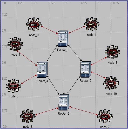
Start by creating for a simple RIP scenario. The network should look like the following. You can use the 100BaseT_LAN, ethernet4_slip8_gtwy router, and 100BaseT links from the object palette to build the network. Connect the routers with PPP_DS3 links. For each of the routers, edit its IP routing parameters and export the routing table once at the end of the simulation (it will export to the simulation log. Set the Global Attributes in the simulation window so it is using RIP as the IP Dynamic Routing Protocol, Auto Addressed/Export as the IP Interface Addressing Mode, and disable the RIP Sim Efficiency. The last change will allow the routing tables to continue to update if there is a change in the network topology.
Set the scenario to collect the global statistics for RIP traffic sent and traffic received and the node statistic for the total number of route table updates. Run the simulation for several minutes and take a look at the results. You can zoom in on the traffic sent and traffic received by opening the Show window and dragging a box around a section of the graph - display the traffic sent and the traffic received, zoom in on a section of two minutes or so of each graph, and explain why each graph looks like it does, based on what you know about the RIP protocol. Explain the difference between the RIP traffic sent and recieved. You can display the routing table updates for one of the routers; if you show the graph, then right-click on it and select Bar, it's a little easier to use. Pick one of the routers and explain this graph as well.
Now set up a second scenario where you can simulate the failure of one of the point-to-point links between routers. You can copy the first scenario, open the Object Palette, select the Utilities page, and add a Failure Recovery object to the network. Edit the failure object, add a row to the Link Failure/Recovery Specification that causes one of the links connecting two routers to fail. Run the second scenario and compare the results of the scenarios. Explain the differences in the total number of updates and the total RIP traffic received between the two scenarios.
You can also take a look at the actual routing tables for each scenario. First, since the scenarios are set to auto-assign IP addresses, you can determine what the address of each interface is; after running both scenarios, select File ... Model Files ... Refresh Model Directories, then select File ... Open, pick Generic Data File from the drop-down list, and select the ip_addresses file for either your first or second scenario (they should contain identical information). It should open a text viewer that contains all the addressing information - pick a router and copy the addresses for its interfaces into your lab report. Now you can get the routing tables for the same router - open the results and select the simulation log. Explain the difference in the routing table for one of the routers between the two scenarios.
Now copy the second scenario (with the link failure) and change it to use OSPF routing instead of RIP. Remember to change the statistics you gather from RIP to OSPF. Why is there only a Traffic Received statistic for OSPF - why not a Traffic Sent statistic as well, like RIP has? Explain the traffic received graph and explain why it is different from the RIP one. Explain the differences in the total number of routing table updates as well.
Now you can look at another benefit of OSPF, allowing multiple routes between the same pair of routers. For these scenarios, you can create a different network, shown below. Use the routers pull-down in the Object Palette to get slip8_gtwy routers, and connect them with the same PPP_DS3 links.
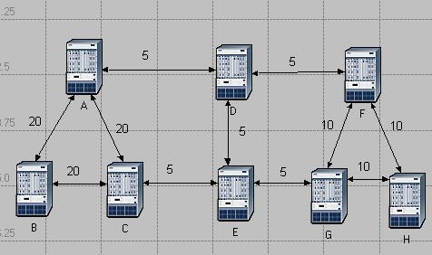
You can configure the link costs of these links - this is calculated by default using the equation
Cost = (reference bandwidth) / (link bandwidth)where the default reference bandwidth is 1,000,000 Kbps. So select the links that are supposed to have cost 5, then select Protocols ... IP ... Routing ... Configure Interface Metric Information. Entering 200000 for the bandwidth would generate a cost of 5 for the link. Make sure that you check the radio button for Interfaces across selected links so it only does the ones you selected. Set the cost for the other links.
Now set up some traffic on the network. Select routers A and C, then select Protocols ... IP ... Demands ... Create Traffic Demands. You can set the traffic parameters in there - I didn't try the full mesh, I just selected From A. Repeat to create a demand from router B to H.
You can force every router to use OSPF by selecting Protocols ... IP ... Routing ... Configure Routing Protocols. Make sure OSPF is checked and RIP is unchecked. You can also turn off Visualize Routing Domains; if you leave it on, it will add some interesting annotations to the network.
Run the scenario, then look at the route that was chosen. You can do this by selecting Protocols ... IP ... Demands ... Display Routes for Configured Demands. Select the route from A to C, and change the Display to Yes. It will indicate the route on the network diagram. Explain why the route that you see was chosen. Check the route from B to H - does that route make sense?
Now copy the scenario and set it so OSPF can use load balancing. If you select routers B and H, then select Protocols ... IP ... Routing ... Configure Load Balancing Options, you can set the load balancing option to Packet Based for the selected routers. Run this simulation and check the route between B and H. Explain the route or routes that are chosen.
Copy this scenario to another one and add some additional traffic to the network - if you add demand between any routers other than D and E, it may have an effect on the route that is chosen between B and H. Run a simulation, describe what traffic you added, and how it affected the route between B and H.
Your lab report should include the following information:
Make sure that you are following Anthony's submission guidelines. Write up a reasonable lab report. As you discovered last week, you'll need to save the report as a PDF file so it is a reasonable size.
The lab write-up is due by the end of the day Wednesday (i.e. 11:59 PM) for the Tuesday lab section and by the end of the day Friday for the Thursday lab section.