|
MODULE I: ABIOTIC PROCESSES
Session I-3
Multiphase flow concepts
Next Session | Previous Session | Table of Contents
Introduction.
The previous session provided a review of important concepts for the case of saturated, single phase (water only) flow through porous media. In the vadose zone (the variably saturated zone lying above the water table) both air and water are present in variable amounts within the soil pore space and a 2-phase system exists. Please refer to Fetter, Chapter 4 for a detailed discussion of flow and mass transport concepts in the vadose zone. The INRA Core course will provide additional background on vadose zone hydrology.Material presented in this session will focus on the multiphase flow concepts which govern the behavior of non aqueous phase liquids (NAPL’s) when they are released into the subsurface as shown in Figure I-1. In these subsurface systems the soil pore space may simultaneously contain variable amounts of air, water, and NAPL. In this session we will focus on the fluid physics which control the displacement of NAPL’s once they are released into the subsurface and have reached static equilibrium. These critical fluid physics concepts include capillarity, capillary pressure, capillary pressure-saturation relationships, and entry pressure. It will be shown in this session that NAPL’s, once released into the subsurface, are extremely hard to remove (totally) by physical methods such as pumping.
Reading Assignment. Please read selected material form Chapter 5, Contaminant Hydrogeology (C. W. Fetter, Prentice Hall, 2nd ed., 1999), and Chapter 2 Natural Attenuation of Fuels and Chlorinated Solvents (Wiedemeier et al., John Wiley and Sons, 1999) as indicated below.
Format.
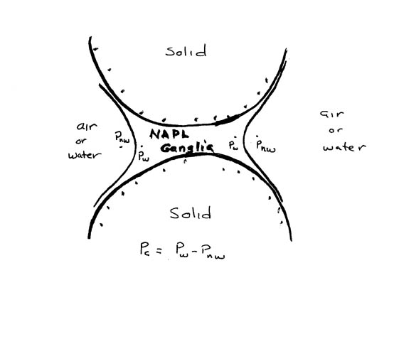
This session will consist of a series of targeted readings from the text books, together with several annotated figures. The reader will be directed to read specific text book sections or figures, then a series of observations and questions will be posed to help underscore important concepts relevant to Subsurface Contaminant Bioremediation.Multiphase flow concepts. Read sections 5.1 through 5.2.3 in Fetter. Pay particular to the definitions for the following terms: saturation ratio, interfacial tension, and capillary pressure. Refer now to Figure I-8 below.
|
Several important observations can be made from Figure I-8. For example it is seem that the NAPL blob or "ganglia" is held to the solid surface by adhesion (the attractive force between two different substances). This adhesive force causes the NAPL molecules to "stretch apart" as the ganglia comes to static equilibrium thereby creating a condition of tension within the NAPL. Therefore if the pressure inside the NAPL is "negative" compared to atmospheric pressure. This condition is analogous to the air-water system shown in section 4.6.5 (pg 183-184) of Fetter, which shows negative gage pressures being measured by a tensiometer in variably saturated soil (Figure 4.9). In Figure I-8 the NAPL is called the "wetting fluid", which means that the NAPL was adhered to an initially dry soil surface. The water phase in Figure I-8 is called the "non-wetting" fluid and, conversely, this implies that the water phase entered the porous media after the NAPL phase was in place. In a system of this kind it is usually safe to assume that the non-wetting phase is under positive gage pressure (in the case of the air water system in Figure 5.2 (pg 211) Fetter, the air (non-wetting phase) is at zero gage pressure). For additional information on the wetting vs non-wetting fluid concept refer to Figure 5.5 (pg 214) in Fetter.
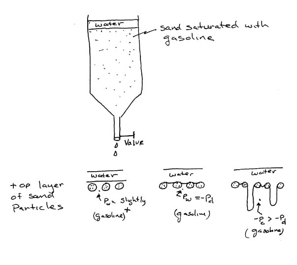
Now look at the definition of capillary pressure defined by equation 5.2 (Fetter), which says that capillary pressure is equal to wetting fluid pressure minus non wetting fluid pressure. Equation 5.2 therefore implies that capillary pressure, Pc, will always be a negative gage pressure. Capillary pressure is plotted as a function of wetting and non-wetting fluid saturation ratios in Figure 5.3 (pg 212), Fetter. Consider the sketch shown in Figure I-9 below.
|
In Figure I-9 the gasoline is the wetting phase and the water is the non-wetting phase. If a valve located at the bottom of the column is now opened slightly gasoline will leave the column. As this happens the gasoline in the column will continue to adhere to the soil surface and eventually, the gage pressure of the gasoline will become negative. Simultaneously water begins enters the column under positive gage pressure, exactly like the condition shown in Figure 1-8, and this results in a (negative ) capillary pressure as defined by equation 5.2 (Fetter). Now in order for any water to initially enter the column it is necessary for the interfacial tension of the gasoline to be exceeded. In other words enough water must flow out of the value so that the capillary pressure becomes high (negative) enough to overcome the interfacial (surface) tension of the gasoline at the top layer of the column. This threshold value of capillary pressure is termed entry pressure, Pd, ( or alternatively displacement pressure, imbibition pressure, or bubbling pressure as shown on pg 211 of Fetter).
Now look at the drainage curve in Figure 5.3 and realize that that this curve could be developed using the system shown in Figure I-9. Assume that the column is initially 100% saturated (i.e. Sw = 100%) with wetting fluid (i.e. gasoline in Figure I-9), and that the corresponding capillary pressure Pc = 0. This point corresponds to the lower right hand corner of Figure 5.3 (Fetter). Now if gasoline is removed from the bottom of the Figure I-9 column as previously explained, the capillary pressure will become increasingly more negative, until it reaches the entry pressure, Pd, for the column. Note in Figure 5.3 that the column stays 100% saturated with wetting fluid (gasoline), until the capillary pressure reaches Pd. Only then can the interfacial tension of the wetting fluid at the top layer of the column be overcome and allow non-wetting fluid (i.e. water in Figure I-9) to enter the column and displace some of the gasoline. As wetting fluid continues to be removed for the column in Figure I-9, the capillary pressure will continue to become increasingly more negative and saturation ratio for the wetting fluid will drop below 100%, as defined by the drainage curve in Figure 5.3. Simultaneously the saturation ratio for the non-wetting fluid will increase as Sw + Snw must equal 100% for this two-phase system. As wetting fluid continues to be removed from the bottom of the column in Figure I-9, the drainage curve in figure 5.3 (Fetter) becomes asymptotic to the irreducible wetting fluid saturation, Swi. This is the saturation ratio of wetting fluid which will not drain out of the column but instead is held in place by capillary forces. The corresponding value of non-wetting fluid saturation ratio, given by 100% - Swi, represents the maximum amount of non-wetting fluid which can be added to the system.
Questions:
I-6. What is the value of entry pressure shown in Figure 5.3 (Fetter)? (about –6 cm of water). What is the wetting and non-wetting fluid saturation ratios corresponding to a capillary pressure value in Figure 5.3 of –20 cm of water? (40%, 60%).
I-7. What value of irreducible wetting fluid saturation is shown in Figure 5.3? (about 25%). If the porosity is 30% what is the volume of wetting fluid contained in a cubic meter of soil at the irreducible wetting fluid value of 25%? ( ).
Now assume that the column in Figure I-9 is at the irreducible wetting fluid saturation condition. If we now begin to add gasoline (i.e. wetting fluid) into the top of the column we will see that the gasoline begins to enter the porous media and displace the water phase, as water continues to move out of the valve at the bottom. This condition corresponds to the imbibition curve in Figure 5.3 (Fetter). Note that as wetting fluid is added the wetting fluid saturation ratio increases from the initial Swi value. Simultaneously the capillary pressure becomes less negative ( this is because more wetting fluid is now present in the porous media thereby causing wetting fluid pressure, Pw, to become less negative). Note also that the imbibition curve does not correspond with the drainage curve due to a hysterisis –type effect. As wetting fluid continues to be added to the column the imbibition curve continues to develop until it terminates at the value of the residual saturation of non-wetting fluid, Snwr. (about 13% in Figure 5.3, Fetter).
Please note the experimentally derived capillary pressure—wetting fluid saturation curves for various two phase systems shown in Figure 5.4 (pg 213). These curves illustrate the variability found due to different soil types and fluid phases.
Now read section 5.2.4, pg 212, which discusses the concept of relative permeability in a multiphase porous media system. Relative permeability is the ratio of the intrinsic permeability for the fluid (either wetting or non-wetting) to the total intrinsic permeability of the porous media. Again consider a conceptual system like in Figure I-9 to help visualize the concept of relative permeability. The relative permeability concept is further illustrated by Figure 5.6, pg 215 (Fetter). Darcy’s law for two phase flow is given in section 5.2.5 pg 217 (Fetter)
.
Question.
I-8. Refer to the system in Figure I-9 and try to visualize how the two fluid are moving through the column at various levels of wetting fluid saturation. Try to rationalize how the relative permeability curves in Figure 5.6 could be developed from the Figure I-9 system. Referring again to Figure 5.6 what is the relative permeability of the wetting fluid when the wetting fluid saturation ratio is equal to or less than the irreducible saturation ? (zero). Why is it zero? In other words, what fluid physical forces cause the relative permeability of the wetting phase to be zero for this condition? (capillarity, surface tension, adhesion, capillary pressure).
NAPL plumes in the subsurface. Refer back to Figure I-1 which shows how LNAPL’s and DNAPL’s might be distributed following their release and infiltration into the subsurface. The multiphase flow concepts which you’ve just learned all have significant implications concerning the migration and remediation of NAPL’s. To conclude this session spend some time thinking about how each of the following concepts influence the movement, distribution, and recovery (i.e. via pumping) of NAPL’s.
·
Capillarity, capillary pressure, adhesion, surface (interfacial) tension·
Wetting vs non-wetting fluid·
Entry pressure·
Capillarity, capillary pressure, adhesion, surface (interfacial) tension·
Irreducible wetting fluid saturation,·
residual saturation of non-wetting fluid·
relative permeability
Questions.
I-9. Which of the above influence vertical migration of NAPL’s resulting from a surface release? (Capillarity, capillary pressure, adhesion, surface (interfacial) tension, Entry pressure, Wetting vs non-wetting fluid). Explain how.
I-10. Which of the above properties directly influence how much NAPL can be extracted by pumping? (Irreducible wetting fluid saturation (if NAPL is wetting phase), residual saturation of non-wetting fluid (if NAPL is non-wetting phase), Capillarity, capillary pressure, adhesion, surface (interfacial) tension, relative permeability) Explain how.